ATTENTION: Due to increased demand and order volume, processing time may take an additional 1-3 business days.
HomeCommunitySubjectNE555P Timer/Oscillator 100KHZ 8-DIP: Datasheet, Pinout, Equivalents, and NE555N VS NE555P

NE555P Timer/Oscillator 100KHZ 8-DIP: Datasheet, Pinout, Equivalents, and NE555N VS NE555P

Clock/Timing - Programmable Timers and Oscillators 8-DIP (0.300, 7.62mm) 100kHz NE555 4.5V~16V 0°C~70°C TEXAS INSTRUMENTS NE555PTIMER SINGLE PRECISION,DIP8 ,0.5MHZ

3065

Dec 7, 2021

Page Petty

Top 10 Easy Electronics Projects using NE555P Timer IC for Beginners


Clock/Timing - Programmable Timers and Oscillators 8-DIP (0.300, 7.62mm) 100kHz NE555 4.5V~16V 0°C~70°C TEXAS INSTRUMENTS NE555PTIMER SINGLE PRECISION,DIP8 ,0.5MHZ

NE555P is a precision timing circuit capable of producing accurate time delays or oscillation. This article is going to introduce pinout, applications, features, and more details about NE555P.

Inquiry
Min.: 1 Mult.: 1
Price not displayed? Not available to buy online? Please send an RFQ, and we will respond immediately.
Quick Links

NE555 Description

NE555 devices are precision timing dircuits capable of producing accurate time delays or oscillation. In the time-delay or mono-stable mode of operation,the timed interval is controlled by a single external resistor and capacitor network. In the a-stable mode of operation,the frequency and duty cycle can be controlled independently with two external resistors and a single external capacitor. The threshold and trigger levels normally are two- thirds and one-third,respectively, of Vcc. These levels can be altered by use of the control-voltage terminal. When the trigger input falls below the trigger level, the flip-flop is set, and the output goes high. If the trigger input is above the trigger level and the threshold input is above the threshold level, the flip- flop is reset and the output is low. The reset (RESET) input can override all other inputs and can be used to initiate a new timing cycle. When RESET goes low, the flip-flop is reset, and the output goes low. When the output is low,a lowimpedance path is provided between discharge (DISCH) and ground. The output circuit is capable of sinking or sourcing current up to 200 mA. Operation is specified for supplies of 5 V to 15 V.With a 5-V supply,output levels are compatible with TTL inputs.

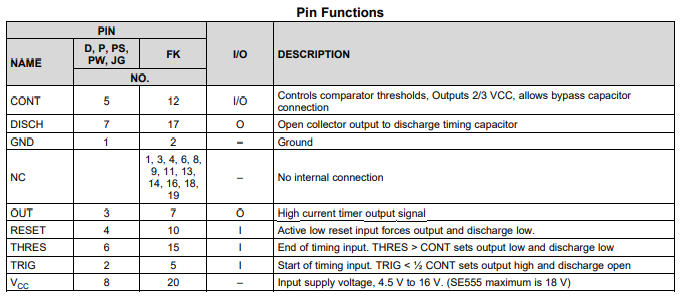
NE555 Pins

NE555 Features

  • Timing From Microseconds to Hours

  • producing accurate time delays or oscillation. In the

  • Astable or Monostable Operation time-delay or mono-stable mode of operation, the

  • Adjustable Duty Cycle timed interval is controlled by a single external

  • TTL-Compatible Output Can Sink or Source resistor and capacitor network. In the a-stable mode Up to 200 mA of operation, the frequency and duty cycle can be controlled independently with two external resistors

  • On Products Compliant to MIL-PRF-38535, and a single external capacitor. All Parameters Are Tested Unless Otherwise Noted. On All Other Products, Production The threshold and trigger levels normally are twoProcessing Does Not Necessarily thirds and one-third, respectively, of VCC. These Include levels can be altered by use of the control-voltage Testing of All Parameters


Specifications

Texas Instruments NE555P technical specifications, attributes, parameters and parts with similar specifications to Texas Instruments NE555P.

undefined Tech Specifications

undefined undefined technical specifications, attributes, parameters and parts with similar specifications to undefined undefined.

Product Attribute Attribute Value
0 Products View Similar

NE555 Applications

  • Fingerprint Biometrics 

  • Iris Biometrics 

  • RFID Reader


The NE555 timer devices use resistor and capacitor charging delay to provide a programmable time delay or operating frequency. This section presents a simplified discussion of the design process. 


Missing-Pulse Detector 

The circuit shown in Figure 1 can be used to detect a missing pulse or abnormally long spacing between consecutive pulses in a train of pulses. The timing interval of the monostable circuit is re-triggered continuously by the input pulse train as long as the pulse spacing is less than the timing interval. A longer pulse spacing, missing pulse, or terminated pulse train permits the timing interval to be completed, thereby generating an output pulse as shown in Figure 2:

Figure 1

Figure 2


Datasheet PDF

Download datasheets and manufacturer documentation for Texas Instruments NE555P.

undefined Documents

Download datasheets and manufacturer documentation for

TAGS

Share