IC OSC SGL TIMER 100KHZ 8TSSOP
The NE555PWR timer is popular and easy to use for general-purpose timing applications from 10 µs to hours or from < 1mHz to 100 kHz.

IC OSC SGL TIMER 100KHZ 8TSSOP The NE555PWR timer is popular and easy to use for general-purpose timing applications from 10 μs to hours or from < 1mHz to 100 kHz.
269
Feb 25, 2021
Cadi
IC OSC SGL TIMER 100KHZ 8TSSOP
The NE555PWR timer is popular and easy to use for general-purpose timing applications from 10 µs to hours or from < 1mHz to 100 kHz.
NE555PWR
| Quantity | Unit Price | Ext. Price |
|---|---|---|
| 1+ | $0.24767 | $0.25 |
| 10+ | $0.23365 | $2.34 |
| 100+ | $0.22043 | $22.04 |
| 500+ | $0.20795 | $103.98 |
| 1000+ | $0.19618 | $196.18 |
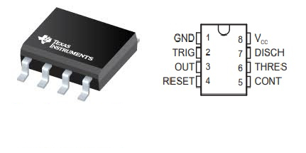
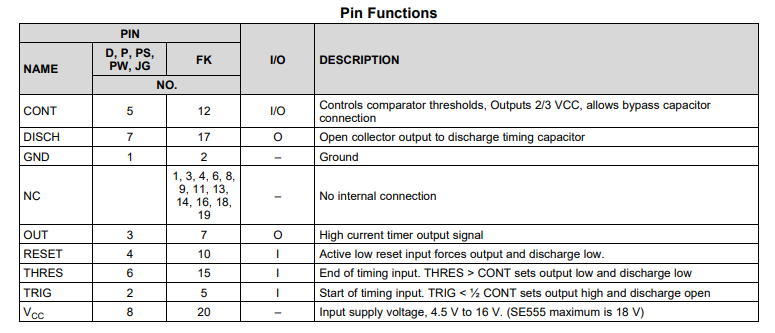
The NE555PWR is a precision timing circuit capable of producing accurate time delays or oscillations. In the time-delaying or mono-stable mode of operation, the timed interval is controlled by a single external resistor and capacitor network. In the a-stable mode of operation, the frequency and duty cycle can be controlled independently with two external resistors and a single external capacitor.
The threshold and trigger levels normally are two-thirds and one-third, respectively, of Vcc. These levels can be altered by the use of the control voltage terminal. When the trigger input falls below the trigger level, the flip-flop is set, and the output goes high. If the trigger input is above the threshold level, the flip-flop is reset and the output is low. The reset RESET) input can override all other inputs and can be used to initiate a new timing cycle. When RESET goes low, the flip-flop is reset, and the output goes low. When the output is low, a low-impedance path is provided between discharge (DISCH) and ground.
The output circuit is capable of sinking or sourcing current up to 200mA. Operation is specified for supplies of 5V to 15V. With a 5V supply, output levels are compatible with TTL inputs.
•Timing from microseconds to hours
•A-stable or mono-stable operation
•Adjustable Duty Cycle
•TTL-Compatible output can sink or source up to 200mA
•On products compliant to MIL-PRF-38535, all parameters are tested unless otherwise noted. On all other products, production processing does not necessarily include testing of all parameters
In the time-delay or mono-stable mode of operation, the timed interval is controlled by a single external resistor and capacitor network. In the a-stable mode of operation, the frequency and duty cycle can be controlled independently with two external resistors and a single external capacitor. Maximum output sink and discharge sink current is greater for higher VCC and less for lower VCC.
•Fingerprint Biometrics
•Iris Biometrics
•RFID Reader
Texas Instruments NE555PWR technical specifications, attributes, parameters and parts with similar specifications to Texas Instruments NE555PWR.
Texas Instruments NE555PWR technical specifications, attributes, parameters and parts with similar specifications to Texas Instruments NE555PWR.
| Product Attribute | Attribute Value | |
|---|---|---|
| Lifecycle Status | ACTIVE (Last Updated: 5 days ago) | |
| Factory Lead Time | 6 Weeks | |
| Contact Plating | Gold | |
| Mount | Surface Mount | |
| Mounting Type | Surface Mount | |
| Package / Case | 8-TSSOP (0.173, 4.40mm Width) | |
| Number of Pins | 8Pins | |
| Weight | 39.008944mg | |
| Operating Temperature | 0°C~70°C | |
| Packaging | Tape & Reel (TR) | |
| JESD-609 Code | e4 | |
| Pbfree Code | yes | |
| Part Status | Active | |
| Moisture Sensitivity Level (MSL) | 1 (Unlimited) | |
| Number of Terminations | 8Terminations |
| Product Attribute | Attribute Value | |
|---|---|---|
| ECCN Code | EAR99 | |
| Type | 555 Type, Timer/Oscillator (Single) | |
| Voltage - Supply | 5V | |
| Terminal Position | DUAL | |
| Terminal Form | GULL WING | |
| Peak Reflow Temperature (Cel) | 260 | |
| Number of Functions | 1Function | |
| Terminal Pitch | 0.65mm | |
| Frequency | 100kHz | |
| Base Part Number | NE555 | |
| Pin Count | 8 | |
| Number of Channels | 1Channel | |
| Nominal Supply Current | 2mA | |
| Quiescent Current | 15mA | |
| Current - Supply | 10mA |
| Product Attribute | Attribute Value | |
|---|---|---|
| High Level Output Current | -200mA | |
| Low Level Output Current | 200mA | |
| Max Junction Temperature (Tj) | 150°C | |
| Voltage - Supply (Min) | 4.5V | |
| Ambient Temperature Range High | 70°C | |
| Height | 1.2mm | |
| Length | 3mm | |
| Width | 4.4mm | |
| Thickness | 1mm | |
| REACH SVHC | No SVHC | |
| Radiation Hardening | No | |
| RoHS Status | ROHS3 Compliant | |
| Lead Free | Lead Free |
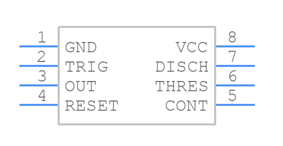
Symbol
Footprint

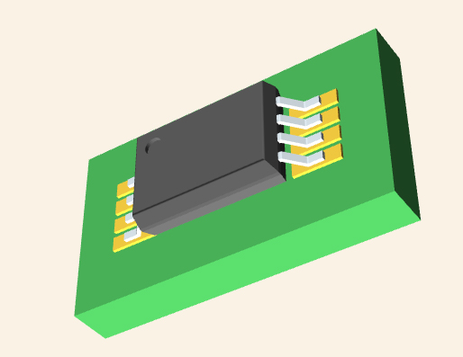
3D Model
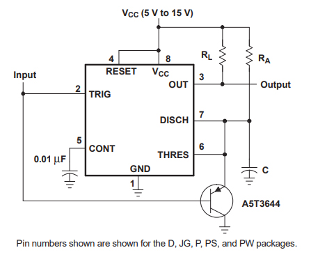
•Circuit for Missing-Pulse Detector
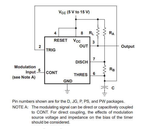
•Circuit for Pulse-Width Modulation
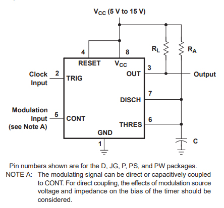
•Circuit for Pulse-Position Modulation
As a global semiconductor company operating in 35 countries, Texas Instruments (TI) is first and foremost a reflection of its people. From the TIer who unveiled the first working integrated circuit in 1958 to the more than 30,000 TIers around the world today who design, manufacture, and sell analog and embedded processing chips, we are problem-solvers collaborating to change the world through technology.
Download datasheets and manufacturer documentation for Texas Instruments NE555PWR.
Download datasheets and manufacturer documentation for NE555PWR
TAGS
Comments