ATTENTION: Due to increased demand and order volume, processing time may take an additional 1-3 business days.
HomeCommunitySubjectPC817 Photocoupler : Application, Pinout and Datasheet

PC817 Photocoupler : Application, Pinout and Datasheet

OPTOISOLATOR 5KV TRANS 4DIP Hello everyone! I hope you all will be absolutely fine and have fun.

1158

Jul 27, 2021

Trista Hewlett

How to test photocoupler PC817/ optocoupler >optocoupler PC817


OPTOISOLATOR 5KV TRANS 4DIP

Hello everyone! I hope you all will be absolutely fine and have fun. Today, I am going to give you a detailed Introduction to PC817. This article mainly introduce application, schematic, datasheet and other detailed information about Shap Microelectronics PC817.

PC817X

Inquiry
Min.: 1 Mult.: 1
Price not displayed? Not available to buy online? Please send an RFQ, and we will respond immediately.
Quick Links

PC817 Description

PC817 Optocoupler also called photocouplers & optoisolators, an IC kind of seeing tools available from 4 pins to many numbers of pins, they are commonly used for the separation of two circuits from each other. 


It consists of Infrared Emitting Diode (IRED). This IRED is coupled to a photo transistor optically and not electrically. It is closed in a four (4) pin package. This package is usually available in two different forms. 


The first one is wide lead (Pb) spacing option and the second one is SMT gullwing lead form option. PC817 has an internal LED and a photo transistor. The photo transistor's base becomes activate when LED throws light on it. The output obtained can be divided into two formats either common emitter or common collector. But the configuration is mostly common emitter. If the LED does not glow, transistor remains off and hence there will b no output generated by the optocoupler i.e. PC817. 


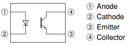
PC817 is a commonly used Optocoupler, it contains one IR LED and one phototransistor in its package. Its working is easy, when a user to apply voltage to the IR LED which is connected to pin 1 and 2 the LED becomes activated and the light is received by the inter phototransistor, therefore, manufacture it in a saturation state due to which it connects the pin 3 and 4 with each other.


PC817 Pinout

PC817 CAD Model

Footprint

PC817 Features

★Input Diode Forward Voltage: 1.25V

★Maximum Collector-Emitter Voltage: 80V

★ Maximum Collector Current(IC): 50mA

★ Cut-off frequency: 80 kHz

★ Rise Time: 18us

★ Fall Time: 18us

★ Package-Type: 4 Pin Dip through hole and SMT

★ Transistor Types of NPN

★ Collector-Emitter Saturation Voltage: 0.1 to 0.2

★ Max Emitter-Collector Voltage (VEBO): 6Volt

★ Max Collector Dissipation (Pc): 200 MW

★ Maximum Storage and Operating temperature Should Be: -55 to +120 Centigrade for storage & -30 to +100 for operating

★ Double transfer mold package (Ideal for Flow Soldering)

Specifications

Sharp Microelectronics PC817X technical specifications, attributes, parameters and parts with similar specifications to Sharp Microelectronics PC817X.

PC817X Tech Specifications

Sharp Microelectronics PC817X technical specifications, attributes, parameters and parts with similar specifications to Sharp Microelectronics PC817X.

Product Attribute Attribute Value
MountThrough Hole
Mounting TypeThrough Hole
Package / Case4-DIP (0.300, 7.62mm)
Number of Pins4Pins
Collector-Emitter Breakdown Voltage35V
Collector-Emitter Saturation Voltage200mV
Current Transfer Ratio-Min50% @ 5mA
Power Dissipation (Max)200mW
Number of Elements1 Element
Operating Temperature-30°C~100°C
PackagingTube
Published2003
JESD-609 Codee0
Product Attribute Attribute Value
Part StatusObsolete
Moisture Sensitivity Level (MSL)1 (Unlimited)
Terminal FinishTin/Lead (Sn/Pb)
Approval AgencyUL
Voltage - Isolation5000Vrms
Output Voltage80V
Output TypeTransistor
ConfigurationSINGLE
Power Dissipation200mW
Voltage - Forward (Vf) (Typ)1.2V
Input TypeDC
Forward Current50mA
Output Current per Channel50mA
Product Attribute Attribute Value
Rise Time18μs
Fall Time (Typ)18 μs
Collector Emitter Voltage (VCEO)80V
Max Collector Current50mA
Rise / Fall Time (Typ)4μs 3μs
Reverse Breakdown Voltage6V
Max Input Current50mA
Max Breakdown Voltage35V
Current Transfer Ratio (Max)600% @ 5mA
REACH SVHCYes
Radiation HardeningNo
RoHS StatusNon-RoHS Compliant
Lead FreeContains Lead
0 Products View Similar

Where to use PC817?

PC817 Photocoupler has a transistor which is controlled based on light (photon). So this IC basically has an IR (infrared) LED and a photo-transistor inside it. When the IR LED is powered the light from it falls on the transistor and it conducts. The arrangement and pinouts of the IR LED and the photo-transistor is shown below.

This IC is used to provide electrical isolation between two circuits, one part of the circuit is connected to the IR LED and the other to Photo-transistor. The digital signal given to the IR LED will be reflected on the transistor but there will be no hard electrical connection between the two. This comes in very handy when you are trying to isolate a noisy signal from your digital electronics, so if you are looking for an IC to provide optical isolation in your circuit design then this IC might be the right choice for you.


How to use PC817?

Using the PC817 IC is pretty much straight forward, we just have to connect the anode pin of the IR LED (pin 1) to the logic input which has to be isolated and the cathode (pin 2) of the IR led to the ground. Then Pull high the collector pin of the transistor using a resistor (here I have used 1K) and connect the collector pin to the output of your desired logic circuit. The Emitter (pin 4) is grounded.


PC817 Applications

★ Noise coupling circuits

★ Ac/DC Power control

★ I/O switching for MCUs (Micro Controller Units)

★ Noise suppression in switching circuits

★ Signal transmission between circuits of different potentials and impedances

★ Office and home appliances

★ Sensor Circuits

★ The output of Microcontrollers to control devices

★ Digital circuits

★ Power suppliers and chargers

★ Isolation between any type of two circuits

PC817 Package

PC817 Manufacturer

Sharp Microelectronics of the Americas (SMA) drives innovative LCD, optoelectronics, memory, imager, and RF components to market. The world's leading manufacturers of consumer and business technologies look to SMA for the products, expertise, and worldwide support they need to make their visions a reality. SMA, in Camas, Washington, is the microelectronics sales and marketing division of Sharp Electronics Corporation, a wholly owned subsidiary of Sharp Corporation.


Datasheet PDF

Download datasheets and manufacturer documentation for Sharp Microelectronics PC817X.

PC817X Documents

Download datasheets and manufacturer documentation for PC817X

Datasheets
PC817X Series

Frequently Asked Questions

1.What is the difference between optocoupler PC817 and PC817B?
First, the peak forward current is different 1. Optocoupler PC817: The peak forward current (ICE max) of the optocoupler PC817 is 1A. 2. Optocoupler PC817B: The peak forward current (ICE max) of the optocoupler PC817B is 1.5A. Second, the role is different 1. Optocoupler PC817: Optocoupler PC817 is used for signal transmission to reduce circuit interference and simplify circuit design. The purpose is to increase safety. 2. Optocoupler PC817B: The optocoupler PC817B is used as a coupling device, which has the function of completely isolating the upper and lower circuits, and does not affect each other. Third, the application is different 1. Optocoupler PC817: Optocoupler PC817 is widely used in computer terminals, thyristor system equipment, measuring instruments, photocopiers, automatic ticketing, household appliances, such as fans, heaters and other circuits. 2. Optocoupler PC817B: Optocoupler PC817B is widely used in voltage automatic gain loops and voltage stabilizing circuits, as well as photoelectric test circuits and optical control circuits.
2.What is the working principle of PC817?
PC817 is a device that encapsulates infrared light emitting devices, infrared light receiving devices and signal processing circuits in the same socket. When the input electrical signal is applied to the input light emitting device LED, the LED emits light, the light receiving device receives the light signal and converts it into an electrical signal, and then directly outputs the electrical signal, or amplifies and processes the electrical signal to a standard digital level output. The conversion and transmission of "electricity-optical-electricity" are realized. Light is the transmission medium, so the input end and the output end are electrically insulated, which is also called electrical isolation. PC817 is a type of optocoupler. Optical coupler (optical coupler, abbreviated as OC in English) is also called opto-isolator or opto-coupler, abbreviated as optocoupler. It is a device that transmits electrical signals through light.
3.What is the operating current range of the optocoupler PC817 input terminal?
Generally, the current is controlled at 5-20mA, and the maximum is 50mA.
4.How to check the quality of PC817?
First, take the optocoupler and use the multimeter diode file to measure the input terminal, and exchange the red and black test leads. If there is a pressure drop in the forward direction, the reverse direction is cut off. Then it shows that the front-end light-emitting diode is normal. Connect a low voltage 6V (take 4N35 as an example, the specific input voltage is subject to the data manual) at the input end and connect the protection resistor in series. Use a multimeter to adjust to the resistance range, and measure the resistance value at the other output terminal. Disconnect the pre-stage power supply with infinite power (usually at the megohm level), and switch on the pre-stage power supply with a sharp decrease in resistance value, which means that the optocoupler is good. Otherwise it is bad.
5.What is the difference between PC817 and 6N137?
PC817 is an ordinary optocoupler, and 6N137 is a high-speed optocoupler. Generally, the communication frequency is not high, you can use PC817 or TL521.
FAQ
1.What is the difference between optocoupler PC817 and PC817B?
First, the peak forward current is different 1. Optocoupler PC817: The peak forward current (ICE max) of the optocoupler PC817 is 1A. 2. Optocoupler PC817B: The peak forward current (ICE max) of the optocoupler PC817B is 1.5A. Second, the role is different 1. Optocoupler PC817: Optocoupler PC817 is used for signal transmission to reduce circuit interference and simplify circuit design. The purpose is to increase safety. 2. Optocoupler PC817B: The optocoupler PC817B is used as a coupling device, which has the function of completely isolating the upper and lower circuits, and does not affect each other. Third, the application is different 1. Optocoupler PC817: Optocoupler PC817 is widely used in computer terminals, thyristor system equipment, measuring instruments, photocopiers, automatic ticketing, household appliances, such as fans, heaters and other circuits. 2. Optocoupler PC817B: Optocoupler PC817B is widely used in voltage automatic gain loops and voltage stabilizing circuits, as well as photoelectric test circuits and optical control circuits.
2.What is the working principle of PC817?
PC817 is a device that encapsulates infrared light emitting devices, infrared light receiving devices and signal processing circuits in the same socket. When the input electrical signal is applied to the input light emitting device LED, the LED emits light, the light receiving device receives the light signal and converts it into an electrical signal, and then directly outputs the electrical signal, or amplifies and processes the electrical signal to a standard digital level output. The conversion and transmission of "electricity-optical-electricity" are realized. Light is the transmission medium, so the input end and the output end are electrically insulated, which is also called electrical isolation. PC817 is a type of optocoupler. Optical coupler (optical coupler, abbreviated as OC in English) is also called opto-isolator or opto-coupler, abbreviated as optocoupler. It is a device that transmits electrical signals through light.
3.What is the operating current range of the optocoupler PC817 input terminal?
Generally, the current is controlled at 5-20mA, and the maximum is 50mA.
4.How to check the quality of PC817?
First, take the optocoupler and use the multimeter diode file to measure the input terminal, and exchange the red and black test leads. If there is a pressure drop in the forward direction, the reverse direction is cut off. Then it shows that the front-end light-emitting diode is normal. Connect a low voltage 6V (take 4N35 as an example, the specific input voltage is subject to the data manual) at the input end and connect the protection resistor in series. Use a multimeter to adjust to the resistance range, and measure the resistance value at the other output terminal. Disconnect the pre-stage power supply with infinite power (usually at the megohm level), and switch on the pre-stage power supply with a sharp decrease in resistance value, which means that the optocoupler is good. Otherwise it is bad.
5.What is the difference between PC817 and 6N137?
PC817 is an ordinary optocoupler, and 6N137 is a high-speed optocoupler. Generally, the communication frequency is not high, you can use PC817 or TL521.

TAGS

Share