ATTENTION: Due to increased demand and order volume, processing time may take an additional 1-3 business days.
HomeCommunitySubjectPCF8574T I/O Expander[FAQ+Video]: Datasheet, Alternatives, and Circuit

PCF8574T I/O Expander[FAQ+Video]: Datasheet, Alternatives, and Circuit

NXP PCF8574T/3,512 I/O Expander, 8bit, 100 kHz, I2C, 2.5 V, 6 V, SOIC PCF8574T is a remote 8-bit I/O expander for I2C-bus made by NXP Semiconductors. What do you want to know about it? PCF8574T datasheet?

244

Apr 29, 2022

Ruth Bertie

PCF8574 I2C GPIO Expander Tutorial


NXP PCF8574T/3,512 I/O Expander, 8bit, 100 kHz, I2C, 2.5 V, 6 V, SOIC

PCF8574T is a remote 8-bit I/O expander for I2C-bus made by NXP Semiconductors. What do you want to know about it? PCF8574T datasheet? PCF8574T applications? PCF8574T Manufacturer? PCF8574T circuit? PCF8574T package? OK, Magi will tell them all for you.

PCF8574T/3,512

700In Stock
Min.: 1 Mult.: 1
Quantity Unit Price Ext. Price
1+ $1.84938$1.85
10+ $1.7447$17.45
100+ $1.64595$164.6
500+ $1.55278$776.39
1000+ $1.46489$1464.89
Unit Price:$1.84938
Subtotal: $1.85
Looking for a better price? Want a lower wholesale price? Please send an RFQ, and we will respond immediately.
Quick Links

PCF8574T Description

The PCF8574T IO Expansion Board is used as a remote 8-bit I/O expander for I2C-bus. Up to 8 PCF8574, T IO Expansion Board can be connected to the I2C-bus, providing up to 64 I/O ports.

The PCF8574T IO Expansion Board features allow the use of multi modules connected to the I2C bus at the same time by connecting the pin header and connector.

There is a small potentiometer on board, which can adjust the backlight of LCD1602 or LCD2004, and a jumper cap to control the switch of the LED light.


PCF8574T CAD Models

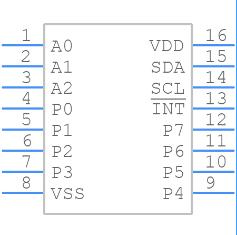
Symbol

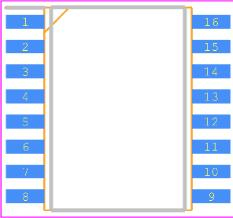
Footprint

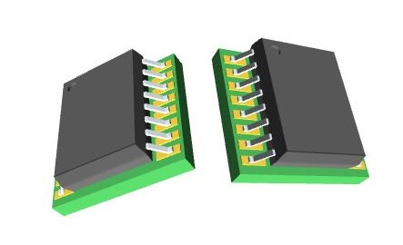
3D Models

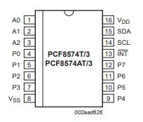
PCF8574T Pinout and Configuration


Pin No Pin Name Description
1 A0 address input 0
2 A1 address input 1
3 A2 address input 2
4 P0 quasi-bidirectional I/O 0
5 P1 quasi-bidirectional I/O 1
6 P2 quasi-bidirectional I/O 2
7 P3 quasi-bidirectional I/O 3
8 VSS supply ground
9 P4 quasi-bidirectional I/O 4
10 P5 quasi-bidirectional I/O 5
11 P6 quasi-bidirectional I/O 6
12 P7 quasi-bidirectional I/O 7
13 INT interrupt output (active LOW)
14 SCL serial clock line
15 SDA serial data line
16 VDD supply voltage

Specifications

NXP USA Inc. PCF8574T/3,512 technical specifications, attributes, parameters and parts with similar specifications to NXP USA Inc. PCF8574T/3,512.

PCF8574T/3,512 Tech Specifications

NXP USA Inc. PCF8574T/3,512 technical specifications, attributes, parameters and parts with similar specifications to NXP USA Inc. PCF8574T/3,512.

Product Attribute Attribute Value
Factory Lead Time7 Weeks
Mounting TypeSurface Mount
Package / Case16-SOIC (0.295, 7.50mm Width)
Surface MountYES
Number of I/Os8I/Os
Operating Temperature-40°C~85°C
PackagingTube
Published1997
JESD-609 Codee4
Part StatusActive
Moisture Sensitivity Level (MSL)2 (1 Year)
Number of Terminations16Terminations
Terminal FinishNickel/Palladium/Gold (Ni/Pd/Au)
Product Attribute Attribute Value
Voltage - Supply2.5V~6V
Terminal PositionDUAL
Terminal FormGULL WING
Peak Reflow Temperature (Cel)260
Supply Voltage5V
Terminal Pitch1.27mm
Time@Peak Reflow Temperature-Max (s)NOT SPECIFIED
Base Part NumberPCF8574
Pin Count16
JESD-30 CodeR-PDSO-G16
Qualification StatusNot Qualified
Output TypePush-Pull
Power Supplies3/5V
Product Attribute Attribute Value
InterfaceI2C
Number of Ports1Port
Number of Bits8Bits
Clock Frequency100kHz
Supply Current-Max0.1mA
External Data Bus Width1
Interrupt OutputYes
Current - Output Source/Sink300μA 25mA
FeaturesPOR
Length10.3mm
Height Seated (Max)2.65mm
Width7.5mm
RoHS StatusROHS3 Compliant
0 Products View Similar

PCF8574T Features

  • 2C-bus to the parallel port expander

  • 100 kHz I2C-bus interface (Standard-mode I2C-bus)

  • Operating supply voltage 2.5 V to 6 V with non-overvoltage tolerant I/O held to VDD with 100 mA current source

  • 8-bit remote I/O pins that default to inputs at power-up

  • Latched outputs directly drive LEDs

  • Total package sink capability of 80 mA

  • The active LOW open-drain interrupt output

  • Eight programmable slave addresses using three address pins

  • Low standby current (2.5 mA typical)

  • -40 ℃ to +85 ℃ operation

  • ESD protection exceeds 2000 V HBM per JESD22-A114 and 1000 V CDM per JESD22-C101

  • Latch-up testing is done to JEDEC Standard JESD78 which exceeds 100 mA

  • Packages offered: DIP16SO16SSOP20

PCF8574T Circuit

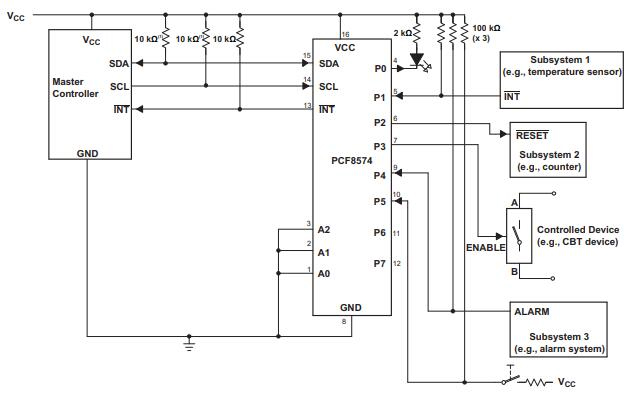
he example circuit diagram is shown in the image below.

  • The main component of the I2C LCD display is the PCF8574 I/O expander, with only two pins SDA and SCL we get a maximum of 8 pins from P0 to P7. PCF8574A also can be used but it has a different address.

  • All LCD data pins are connected to the PCF8574 where: RS, RW, E, D4, D5, D6, and D7 are connected to P0, P1, P2, P4, P5, P6, and P7 respectively.

  • PCF8574 I/O expander SDA and SCL pins are connected to Arduino pins A4 and A5 respectively (Arduino SDA and SCL pins).

  • PCF8574 I/O expander A0, A1, and A2 pins are the address pins that decide the I2C address of the chip. In this example, each pin is connected to +5V through a 10k ohm resistor (the 10k resistor is optional, each pin can be connected directly to +5V).

  • The I2C address of the PCF8574 is: 0x20 | A2 A1 A0 ( | means OR)

  • In our circuit A2, A1 and A0 are connected to +5V (through 10k resistors) which means the I2C address is equal to 0x20 | 7 = 0x27

  • If the PCF8574A is used instead of the PCF8574 the I2C address is: 0x38 | 7 = 0x3F.

PCF8574T Manufacturer

NXP Semiconductors N.V. (NXP) is a Dutch semiconductor designer and manufacturer with headquarters in Eindhoven, Netherlands. The company employs approximately 29,000 people in more than 30 countriesNXP reported revenue of $11.06 billion in 2021.

Originally spun off from Philips in 2006NXP completed its initial public offering, on August 6, 2010, with shares trading on NASDAQ under the ticker symbol NXPI. On December 23, 2013, NXP Semiconductors was added to the NASDAQ 100. On March 2, 2015, it was announced that NXP would merge with Freescale Semiconductor. The merger was closed on December 7, 2015. On October 27, 2016, it was announced that Qualcomm would try to buy NXP. Because the Chinese merger authority did not approve the acquisition before the deadline set by Qualcomm, the attempt was effectively canceled on July 26, 2018.


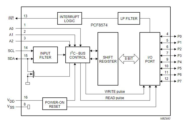
PCF8574T Block Diagram

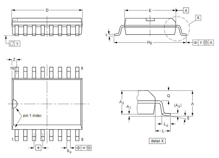
PCF8574T Package

Datasheet PDF

PCF8574T/3,512 Documents

Download datasheets and manufacturer documentation for PCF8574T/3,512

Datasheets
PCF8574
Environmental Information
NXP RoHS3 Cert

Frequently Asked Questions

What is I2C converter?
I2C LCD adapter is a device containing a micro-controller PCF8574 chip.
What is I2c module?
I2C Module has an inbuilt PCF8574 I2C chip that converts I2C serial data to parallel data for the LCD display.
What is I2C used for?
The I2C protocol is used to establish communication between two or more ICs (Integrated Circuits), hence why it's known as Inter-Integrated Circuit (I2C) communication.
How do I program PCF8574?
After connecting the I2C Module to LCD, connect the GND and VCC pins of the PCF8574 Module to the GND and 5V pins of Arduino. Finally, the SDA and SCL Pins. Connect them to pins A4 and A5 pins of Arduino UNO respectively.
What is pcf8574t?
The PCF8574/74A provides general-purpose remote I/O expansion via the two-wire bidirectional I2C-bus (serial clock (SCL), serial data (SDA)). The devices consist of eight quasi-bidirectional ports, a 100 kHz I2C-bus interface, three hardware address inputs, and interrupt output operating between 2.5 V and 6 V.
FAQ
What is I2C converter?
I2C LCD adapter is a device containing a micro-controller PCF8574 chip.
What is I2c module?
I2C Module has an inbuilt PCF8574 I2C chip that converts I2C serial data to parallel data for the LCD display.
What is I2C used for?
The I2C protocol is used to establish communication between two or more ICs (Integrated Circuits), hence why it's known as Inter-Integrated Circuit (I2C) communication.
How do I program PCF8574?
After connecting the I2C Module to LCD, connect the GND and VCC pins of the PCF8574 Module to the GND and 5V pins of Arduino. Finally, the SDA and SCL Pins. Connect them to pins A4 and A5 pins of Arduino UNO respectively.
What is pcf8574t?
The PCF8574/74A provides general-purpose remote I/O expansion via the two-wire bidirectional I2C-bus (serial clock (SCL), serial data (SDA)). The devices consist of eight quasi-bidirectional ports, a 100 kHz I2C-bus interface, three hardware address inputs, and interrupt output operating between 2.5 V and 6 V.

TAGS

Share