ATTENTION: Due to increased demand and order volume, processing time may take an additional 1-3 business days.
HomeCommunitySubjectPIC12F675 Microcontroller: Circuit, Pinout, and Datasheet

PIC12F675 Microcontroller: Circuit, Pinout, and Datasheet

Embedded - Microcontrollers A/D 4x10b 8-DIP (0.300, 7.62mm) 1.8kB POR, WDT -40°C~85°C TA 2V~5.5V PIC? 12F MICROCONTROLLER, RISC PIC12F675 20MHz IC MCU 8BIT 1.75KB FLASH 8DIP

245

Nov 8, 2021

Tess Morley

Getting Started with Programming PIC 12F675


Embedded - Microcontrollers A/D 4x10b 8-DIP (0.300, 7.62mm) 1.8kB POR, WDT -40°C~85°C TA 2V~5.5V PIC® 12F MICROCONTROLLER, RISC PIC12F675 20MHz IC MCU 8BIT 1.75KB FLASH 8DIP

PIC12F675 is an 8-Bit CMOS Microcontroller made by MICROCHIP TECHNOLOGY and is developed on high-performance RISC architecture. This article mainly introduces circuit, pinout, datasheet and other detailed information about Microchip Technology PIC12F675.

PIC12F675-I/P

14725In Stock
Min.: 1 Mult.: 1
Quantity Unit Price Ext. Price
1+ $1.57013$1.57
10+ $1.48125$14.81
100+ $1.39741$139.74
500+ $1.31831$659.16
1000+ $1.24369$1243.69
Unit Price:$1.57013
Subtotal: $1.57
Looking for a better price? Want a lower wholesale price? Please send an RFQ, and we will respond immediately.
Quick Links

PIC12F675 Description

The PIC12F675 is an 8-Bit CMOS Microcontroller made by MICROCHIP TECHNOLOGY and is developed on high-performance RISC architecture. This microcontroller is very popular among hobbyists and engineers due its cost and small size.

The PIC12F675 is a microcontroller developed for low-cost systems and applications. Engineers will benefit from its high flash memory rewrite cycle, which makes it ideal for learning and experimenting. The controller features 2KBytes of flash memory, which is sufficient for beginners to write simple programs. The six GPIO pins are also intended to handle a maximum current of 25mA, which is sufficient for many peripheral devices and sensors.

This controller has a limited set of capabilities and cannot be used to create complex applications. It's great for novices who wish to learn how to program for the microcontroller platform.


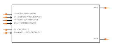
PIC12F675 Pinout

Pinout


Pin Number Pin Name Function Description
7 GP0/AN0/CIN+/ICSPDAT GP0 Bidirectional I/O w/ programmable pull-up and interrupt-on-change
AN0 A/D Channel 0 input
CIN+ Comparator input
ICSPDAT Serial programming I/O
6 GP1/AN1/CIN-/VREF/ICSPCLK GP1 Bidirectional I/O w/ programmable pull-up and interrupt-on-change
AN1 A/D Channel 1 input
CIN- Comparator input
VREF External voltage reference
ICSPCLK Serial programming clock
5 GP2/AN2/T0CKI/INT/COUT GP2 Bidirectional I/O w/ programmable pull-up and interrupt-on-change
AN2 A/D Channel 2 input
T0CKI TMR0 clock input
INT External interrupt
COUT Comparator output
4 GP3/MCLR/VPP GP3 Input port w/ interrupt-on-change
MCLR Master Clear
VPP Programming voltage
3 GP4/AN3/T1G/OSC2/CLKOUT GP4 Bidirectional I/O w/ programmable pull-up and interrupt-on-change
AN3 A/D Channel 3 input
T1G TMR1 gate
OSC2 Crystal/resonator
CLKOUT FOSC/4 output
2 GP5/T1CKI/OSC1/CLKIN GP5 Bidirectional I/O w/ programmable pull-up and interrupt-on-change
T1CKI TMR1 clock
OSC1 Crystal/resonator
CLKIN External clock input/RC oscillator connection
8 VSS VSS Ground reference
1 VDD VDD Positive supply

PIC12F675 CAD Model

Symbol

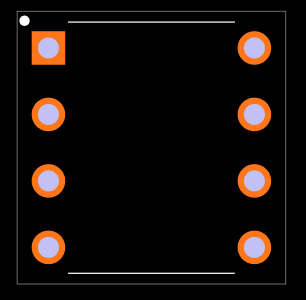
Footprint

3D Model

PIC12F675 Features

(1) High-Performance RISC CPU:

• Only 35 Instructions to Learn

- All single-cycle instructions except branches

• Operating Speed:

- DC - 20 MHz oscillator/clock input

- DC - 200 ns instruction cycle

• Interrupt Capability

• 8-Level Deep Hardware Stack

• Direct, Indirect, and Relative Addressing modes

(2) Special Microcontroller Features:

• Internal and External Oscillator Options

- Precision Internal 4 MHz oscillator factory calibrated to ±1%

- External Oscillator support for crystals and resonators

- 5 μs wake-up from Sleep, 3.0V, typical

• Power-Saving Sleep mode

• Wide Operating Voltage Range – 2.0V to 5.5V

• Industrial and Extended Temperature Range

• Low-Power Power-on Reset (POR)

• Power-up Timer (PWRT) and Oscillator Start-up Timer (OST)

• Brown-out Detect (BOD)

• Watchdog Timer (WDT) with Independent Oscillator for Reliable Operation

• Multiplexed MCLR/Input Pin

• Interrupt-on-Pin Change

• Individual Programmable Weak Pull-ups

• Programmable Code Protection

• High Endurance Flash/EEPROM Cell

- 100,000 write Flash endurance

- 1,000,000 write EEPROM endurance

- Flash/Data EEPROM Retention: > 40 years 

(3) Low-Power Features:

• Standby Current:

- 1 nA @ 2.0V, typical

• Operating Current:

- 8.5 μA @ 32 kHz, 2.0V, typical

- 100 μA @ 1 MHz, 2.0V, typical

• Watchdog Timer Current

- 300 nA @ 2.0V, typical

• Timer1 Oscillator Current:

- 4 μA @ 32 kHz, 2.0V, typical

(4) Peripheral Features:

• 6 I/O Pins with Individual Direction Control

• High Current Sink/Source for Direct LED Drive

• Analog Comparator module with:

- One analog comparator

- Programmable on-chip comparator voltage reference (CVREF) module

- Programmable input multiplexing from device inputs

- Comparator output is externally accessible

• Analog-to-Digital Converter module (PIC12F675):

- 10-bit resolution

- Programmable 4-channel input

- Voltage reference input

• Timer0: 8-Bit Timer/Counter with 8-Bit

Programmable Prescaler

• Enhanced Timer1:

- 16-bit timer/counter with prescaler

- External Gate Input mode

- Option to use OSC1 and OSC2 in LP mode as Timer1 oscillator, if INTOSC mode selected

• In-Circuit Serial Programming™ (ICSP™) via two pins

Specifications

Microchip Technology PIC12F675-I/P technical specifications, attributes, parameters and parts with similar specifications to Microchip Technology PIC12F675-I/P.

PIC12F675-I/P Tech Specifications

Microchip Technology PIC12F675-I/P technical specifications, attributes, parameters and parts with similar specifications to Microchip Technology PIC12F675-I/P.

Product Attribute Attribute Value
Factory Lead Time6 Weeks
MountThrough Hole
Mounting TypeThrough Hole
Package / Case8-DIP (0.300, 7.62mm)
Number of Pins8Pins
Data ConvertersA/D 4x10b
Number of I/Os5I/Os
Watchdog TimersYes
Operating Temperature-40°C~85°C TA
PackagingTube
SeriesPIC® 12F
Published2003
JESD-609 Codee3
Pbfree Codeyes
Part StatusActive
Moisture Sensitivity Level (MSL)1 (Unlimited)
Number of Terminations8Terminations
TerminationThrough Hole
ECCN CodeEAR99
Terminal FinishMatte Tin (Sn)
Product Attribute Attribute Value
Max Power Dissipation800mW
Terminal PositionDUAL
Supply Voltage5V
Frequency20MHz
Base Part NumberPIC12F675
Pin Count8
InterfaceRS-232, USB
Memory Size1.8kB
Oscillator TypeInternal
Nominal Supply Current100μA
RAM Size64 x 8
Voltage - Supply (Vcc/Vdd)2V~5.5V
uPs/uCs/Peripheral ICs TypeMICROCONTROLLER, RISC
Core ProcessorPIC
PeripheralsPOR, WDT
Program Memory TypeFLASH
Core Size8-Bit
Program Memory Size1.75KB 1K x 14
Bit Size8
Access Time20 μs
Product Attribute Attribute Value
Has ADCYES
DMA ChannelsNO
Data Bus Width8b
PWM ChannelsNO
Number of Timers/Counters2Timers/Counters
Address Bus Width8b
Density14 kb
EEPROM Size128 x 8
CPU FamilyPIC
Number of A/D Converters1A/D Converter
Number of Programmable I/O6Programmable I/Os
Number of ADC Channels4ADC Channels
Height4.953mm
Length10.16mm
Width7.112mm
REACH SVHCNo SVHC
Radiation HardeningNo
RoHS StatusROHS3 Compliant
Lead FreeLead Free
0 Products View Similar

PIC12F675 Functional Block Diagram

Functional Block Diagram

How to use PIC12F675 Microcontroller

Before using a microcontroller in a system or application, it must first be programmed. So, first and foremost, we must program the PIC12F675 controller.

The entire procedure for programming the PIC12F675 is as follows:

• First list all the functions to be executed by this controller.

• Next write these functions in ‘IDE software’ using a relative programming language (use ‘C’ language in MPLAB IDE).

• After writing the desired program compile it for error elimination

• For a successful compilation IDE application generates a HEX file for the written program

• Choose the programming device (usually ‘PIC kit 3’ or ‘PIC kit 2’) which establishes communication between PC and PIC12F675

• Connect the programming device to the microcontroller appropriately

• Run the HEX file dumping software which is related to the chosen programming device

• Choose the appropriate program HEX file and burn this HEX file in PIC12F675 flash memory

• Disconnect the programmer and connect the appropriate peripherals for the controller

After plugging in the electricity, the controller runs the HEX code stored in the memory (which is a written program) and generates the desired response.

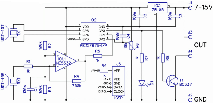
PIC12F675 Ultrasonic Proximity Detector Circuit Diagram

The ultrasonic proximity detector circuit PIC12F675 detects a distance of about 30 cm to 3 m mounted on the microcontroller.

The rotating time of the radiating ultrasonic wave reflected from any object is used to calculate ultrasonic distance. The design is as basic and tiny as feasible, thanks to the Microchip PIC12F675 microcontroller and integrated hardware functionalities, and the circuit is mounted on a PCB board.

The reflected wave connects the signal amplified with the NE5532 to the input of the PIC12F675 microcontroller's inbuilt comparator (pin 6).

An internal reference is set to the comparator and the decision level is modified inside the PIC12F675 Microcontroller. Changing its value (VRCON recording) makes adjusting the circuit's sensitivity to the input signal a breeze. The sensitivity is now tuned to the lowest feasible value thanks to the adoption of a high-quality operational amplifier in the IO1 position.

R6 is attached to the internal A/D converter's input, which continuously monitors its present position. It is utilized as a decision level for measuring the ultrasonic wave's reflection duration, and the software limits it to a range of around 30 cm to 3 m.

The microcontroller output (pin 7) and then the output transistor T1 will open if the reflected wave is set or detected at a lower range/distance, for example, to control the relay, buzzer, or any other system. LED D1 turns on the output, which remains open for the duration of the obstacle detection period within the set distance.

The ultrasonic sensor circuit is designed with DIP and SMD type 2 PCBs. SMD source asm and hex software files come in two flavors: double-layer and single-source.

Ultrasonic Proximity Detector Circuit


PIC12F675 Alternatives

Part Number Description Manufacturer
PIC12F675T-C/SNMICROCONTROLLERS AND PROCESSORS 8-Pin, Flash-Based 8-Bit CMOS Microcontrollers, 0C to +70C, 8-SOIC 150mil, T/R Microchip Technology Inc
PIC12F675-I/SNMICROCONTROLLERS AND PROCESSORS 8-BIT, FLASH, 20 MHz, RISC MICROCONTROLLER, PDSO8, 3.90 MM, ROHS COMPLIANT, PLASTIC, SOIC-8 Microchip Technology Inc
PIC12F675-C/SNMICROCONTROLLERS AND PROCESSORS 8-Pin, Flash-Based 8-Bit CMOS Microcontrollers, 0C to +70C, 8-SOIC 150mil, TUBE Microchip Technology Inc
PIC12F675-I/SNC01GMICROCONTROLLERS AND PROCESSORS 8-BIT, FLASH, 20 MHz, RISC MICROCONTROLLER, PDSO8, 3.90 MM, ROHS COMPLIANT, PLASTIC, SOIC-8 Microchip Technology Inc
PIC12F675-E/SNMICROCONTROLLERS AND PROCESSORS 8-BIT, FLASH, 20 MHz, RISC MICROCONTROLLER, PDSO8, 3.90 MM, ROHS COMPLIANT, PLASTIC, SOIC-8 Microchip Technology Inc

PIC12F675 Applications

• Low-end applications like scrolling display, temperature monitor etc

• Beginner applications

• Hobbyist projects

• Display units

• Development board for learners

PIC12F675 Package

PIC12F675 Manufacturer

Microchip Technology Inc. is a leading provider of microcontroller and analog semiconductors, delivering low-risk product development, reduced overall system cost, and faster time to market to thousands of customers across the world. Microchip, based in Chandler, Arizona, provides excellent technical support as well as consistent delivery and quality.


Datasheet PDF

Download datasheets and manufacturer documentation for Microchip Technology PIC12F675-I/P.

PIC12F675-I/P Documents

Download datasheets and manufacturer documentation for PIC12F675-I/P

Frequently Asked Questions

1.What is the difference between PIC12F675 and PIC12F683?
For the same series, the resources of PIC12F683 are basically double that of PIC12F675. PIC12F675 program: 1.75K, EEPROM: 128, RAM: 64, clock: 4 MHz. PIC12F683 program: 3.5K, EEPROM: 256, RAM: 128, clock: 8 MHz, one more 8-bit timer.
2.What is the difference between PIC12F629 and PIC12F675?
The only difference between the PIC12F629 and the PIC12F675 is that the PIC12F675 contains a 10-bit A/D converter. 8-pin PDIP, SOIC, MLF-S, and DFN packages are available.
3.How to burn PIC12F675 online?
(1) Check the information of PIC12F675 and set the control word to set it as the built-in 4MHZ crystal oscillator; (2) 1.46~2.5V should be high level, 1.45V is low level, just use an if...else... statement.
FAQ
1.What is the difference between PIC12F675 and PIC12F683?
For the same series, the resources of PIC12F683 are basically double that of PIC12F675. PIC12F675 program: 1.75K, EEPROM: 128, RAM: 64, clock: 4 MHz. PIC12F683 program: 3.5K, EEPROM: 256, RAM: 128, clock: 8 MHz, one more 8-bit timer.
2.What is the difference between PIC12F629 and PIC12F675?
The only difference between the PIC12F629 and the PIC12F675 is that the PIC12F675 contains a 10-bit A/D converter. 8-pin PDIP, SOIC, MLF-S, and DFN packages are available.
3.How to burn PIC12F675 online?
(1) Check the information of PIC12F675 and set the control word to set it as the built-in 4MHZ crystal oscillator; (2) 1.46~2.5V should be high level, 1.45V is low level, just use an if...else... statement.

TAGS

Share