ATTENTION: Due to increased demand and order volume, processing time may take an additional 1-3 business days.
HomeCommunitySubjectPIC18F4520 Microcontroller: Features, Pinout, and Datasheet

PIC18F4520 Microcontroller: Features, Pinout, and Datasheet

Embedded - Microcontrollers A/D 13x10b 44-TQFP 32kB Brown-out Detect/Reset, HLVD, POR, PWM, WDT -40°C~85°C TA 4.2V~5.5V PIC? 18F MICROCONTROLLER, RISC PIC18F4520 40MHz IC MCU 8BIT 32KB FLASH 44TQFP

12053

Oct 29, 2021

Theresa

LCD interfacing with PIC18F4520

Embedded - Microcontrollers A/D 13x10b 44-TQFP 32kB Brown-out Detect/Reset, HLVD, POR, PWM, WDT -40°C~85°C TA 4.2V~5.5V PIC® 18F MICROCONTROLLER, RISC PIC18F4520 40MHz IC MCU 8BIT 32KB FLASH 44TQFP

PIC18F4520 is a Microchip PIC microcontroller that is mostly utilized in automation and embedded systems. It is available in three packages: PDIP, QFN, and TQFP. The first is a 40-pin package (which is the most common), while the other two have a 44-pin interface. This article mainly introduces features, pinout, datasheet and other information about Microchip Technology PIC18F4520.

PIC18F4520-I/PT

8000In Stock
Min.: 1 Mult.: 1
Quantity Unit Price Ext. Price
1+ $5.78604$5.79
10+ $5.45852$54.59
100+ $5.14955$514.95
500+ $4.85807$2429.04
1000+ $4.58308$4583.08
Unit Price:$5.78604
Subtotal: $5.79
Looking for a better price? Want a lower wholesale price? Please send an RFQ, and we will respond immediately.
Quick Links

PIC18F4520 Description

PIC18F4520 is a Microchip PIC microcontroller that is mostly utilized in automation and embedded systems. It is available in three packages: PDIP, QFN, and TQFP. The first is a 40-pin package (which is the most common), while the other two have a 44-pin interface. 


This microcontroller version has a CPU, timers, a 10-bit ADC, and other peripherals for developing connections with external devices. This PIC version, like others in the PIC community, includes everything needed to build an embedded system and automate processes.


The PIC18F4520 has 32K of program memory, 256 bytes of EEPROM data memory, 1536 bytes of RAM, and 256 bytes of EEPROM data memory. It also has two comparators, a 10-bit A/D converter with 13 channels, and decent memory endurance of roughly 1,000,000 for EEPROM and 100,000 for program memory. EUSART (Enhanced Universal Asynchronous Receiver Transmitter) is a feature that can be used to develop serial connections with other devices.


The chip includes an asynchronous serial port that can be connected in either direction, using either the 3-wire Serial Peripheral Interface (SPI™) or the 2-wire Inter-Integrated Circuit (I²C™) Bus.

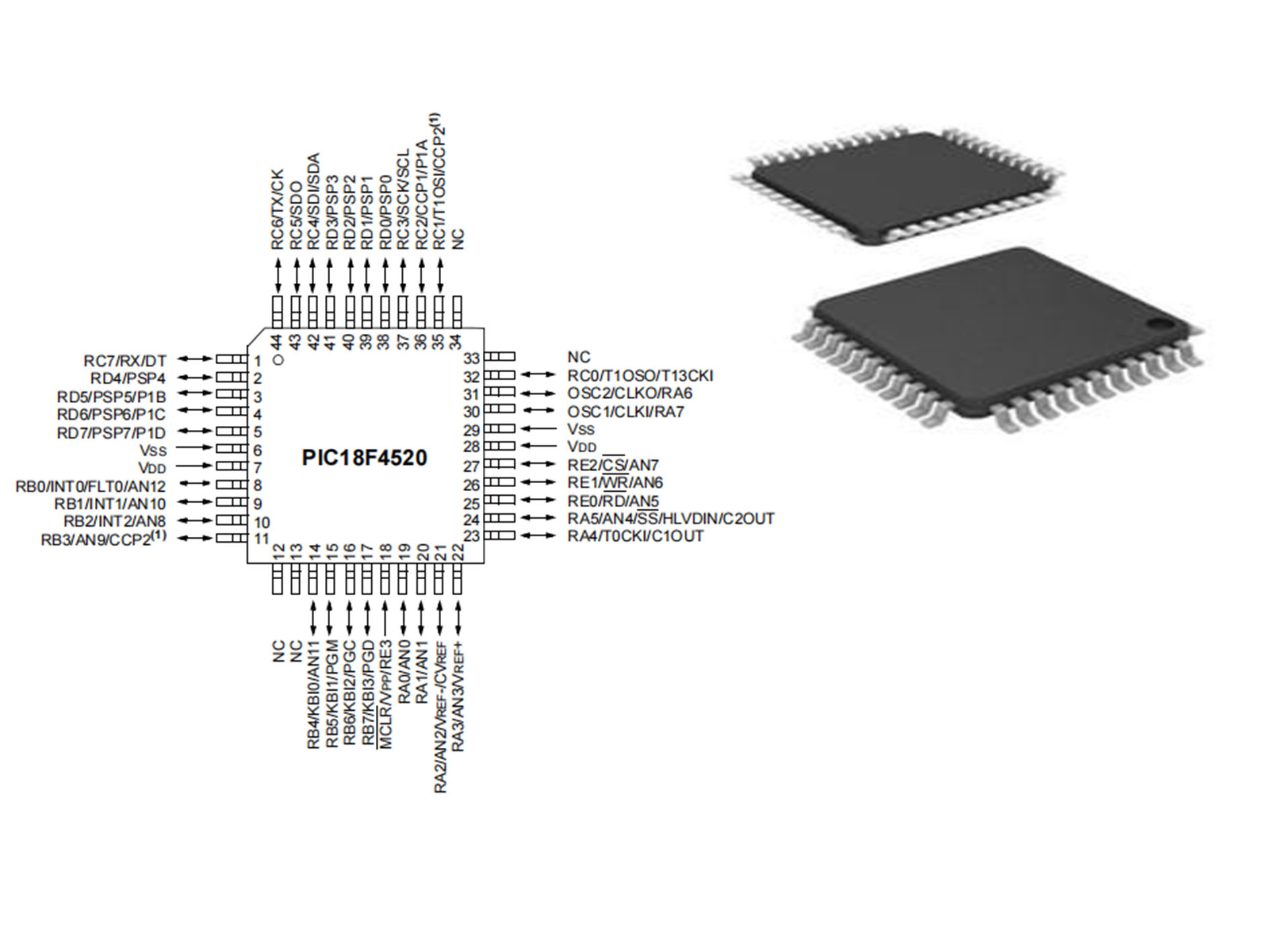
PIC18F4520 Pinout

Pinout


Pin Number Pin Name Description
18 MCLR/VPP/RE3
MCLR
VPP
RE3
Master Clear (input) or programming voltage (input).
Master Clear (Reset) input. This pin is an active-low
Reset to the device.
Programming voltage input.
Digital input.
30 OSC1/CLKI/RA7
OSC1
CLKI
RA7
Oscillator crystal or external clock input.
Oscillator crystal input or external clock source input.
ST buffer when configured in RC mode;
analog otherwise.
External clock source input. Always associated with
pin function, OSC1. (See related OSC1/CLKI,
OSC2/CLKO pins.)
General purpose I/O pin.
31 OSC2/CLKO/RA6
OSC2
CLKO
RA6
Oscillator crystal or clock output.
Oscillator crystal output. Connects to crystal
or resonator in Crystal Oscillator mode.
In RC mode, OSC2 pin outputs CLKO which
has 1/4 the frequency of OSC1 and denotes
the instruction cycle rate.
General purpose I/O pin.
    PORTA is a bidirectional I/O port.
19 RA0/AN0
RA0
AN0
Digital I/O.
Analog input 0.
20 RA1/AN1
RA1
AN1
Digital I/O.
Analog input 1.
21 RA2/AN2/VREF-/CVREF
RA2
AN2
VREF-
CVREF
Digital I/O.
Analog input 2.
A/D reference voltage (low) input.
Comparator reference voltage output.
22 RA3/AN3/VREF+
RA3
AN3
VREF+
Digital I/O.
Analog input 3.
A/D reference voltage (high) input.
23 RA4/T0CKI/C1OUT
RA4
T0CKI
C1OUT
Digital I/O.
Timer0 external clock input.
Comparator 1 output.
24 RA5/AN4/SS/HLVDIN/C2OUT
RA5
AN4
SS
HLVDIN
C2OUT
Digital I/O.
Analog input 4.
SPI slave select input.
High/Low-Voltage Detect input.
Comparator 2 output.
  RA6 See the OSC2/CLKO/RA6 pin.
  RA7 See the OSC1/CLKI/RA7 pin.
    PORTB is a bidirectional I/O port. PORTB can be
software programmed for internal weak pull-ups on all
inputs.
8 RB0/INT0/FLT0/AN12
RB0
INT0
FLT0
AN12
Digital I/O.
External interrupt 0.
PWM Fault input for Enhanced CCP1.
Analog input 12.
9 RB1/INT1/AN10
RB1
INT1
AN10
Digital I/O.
External interrupt 1.
Analog input 10.
10 RB2/INT2/AN8
RB2
INT2
AN8
Digital I/O.
External interrupt 2.
Analog input 8.
11 RB3/AN9/CCP2
RB3
AN9
CCP2(1)
Digital I/O.
Analog input 9.
Capture 2 input/Compare 2 output/PWM2 output.
14 RB4/KBI0/AN11
RB4
KBI0
AN11
Digital I/O.
Interrupt-on-change pin.
Analog input 11.
15 RB5/KBI1/PGM
RB5
KBI1
PGM
Digital I/O.
Interrupt-on-change pin.
Low-Voltage ICSP™ Programming enable pin.
16 RB6/KBI2/PGC
RB6
KBI2
PGC
Digital I/O.
Interrupt-on-change pin.
In-Circuit Debugger and ICSP programming
clock pin.
17 RB7/KBI3/PGD
RB7
KBI3
PGD
Digital I/O.
Interrupt-on-change pin.
In-Circuit Debugger and ICSP programming
data pin.
    PORTC is a bidirectional I/O port.
32 RC0/T1OSO/T13CKI
RC0
T1OSO
T13CKI
Digital I/O.
Timer1 oscillator output.
Timer1/Timer3 external clock input.
35 RC1/T1OSI/CCP2
RC1
T1OSI
CCP2(2)
Digital I/O.
Timer1 oscillator input.
Capture 2 input/Compare 2 output/PWM2 output.
36 RC2/CCP1/P1A
RC2
CCP1
P1A
Digital I/O.
Capture 1 input/Compare 1 output/PWM1 output.
Enhanced CCP1 output.
37 RC3/SCK/SCL
RC3
SCK
SCL
Digital I/O.
Synchronous serial clock input/output for
SPI mode.
Synchronous serial clock input/output for I²C™ mode.
42 RC4/SDI/SDA
RC4
SDI
SDA
Digital I/O.
SPI data in.
I²C data I/O.
43 RC5/SDO
RC5
SDO
Digital I/O.
SPI data out.
44 RC6/TX/CK
RC6
TX
CK
Digital I/O.
EUSART asynchronous transmit.
EUSART synchronous clock (see related RX/DT).
1 RC7/RX/DT
RC7
RX
DT
Digital I/O.
EUSART asynchronous receive.
EUSART synchronous data (see related TX/CK).
    PORTD is a bidirectional I/O port or a Parallel Slave
Port (PSP) for interfacing to a microprocessor port.
These pins have TTL input buffers when PSP module
is enabled.
38 RD0/PSP0
RD0
PSP0
Digital I/O.
Parallel Slave Port data.
39 RD1/PSP1
RD1
PSP1
Digital I/O.
Parallel Slave Port data.
40 RD2/PSP2
RD2
PSP2
Digital I/O.
Parallel Slave Port data.
41 RD3/PSP3
RD3
PSP3
Digital I/O.
Parallel Slave Port data.
2 RD4/PSP4
RD4
PSP4
Digital I/O.
Parallel Slave Port data.
3 RD5/PSP5/P1B
RD5
PSP5
P1B
Digital I/O.
Parallel Slave Port data.
Enhanced CCP1 output.
4 RD6/PSP6/P1C
RD6
PSP6
P1C
Digital I/O.
Parallel Slave Port data.
Enhanced CCP1 output.
5 RD7/PSP7/P1D
RD7
PSP7
P1D
Digital I/O.
Parallel Slave Port data.
Enhanced CCP1 output.
    PORTE is a bidirectional I/O port.
25 RE0/RD/AN5
RE0
RD
AN5
Digital I/O.
Read control for Parallel Slave Port
(see also WR and CS pins).
Analog input 5.
26 RE1/WR/AN6
RE1
WR
AN6
Digital I/O.
Write control for Parallel Slave Port
(see CS and RD pins).
Analog input 6.
27 RE2/CS/AN7
RE2
CS
AN7
Digital I/O.
Chip Select control for Parallel Slave Port
(see related RD and WR).
Analog input 7.
  RE3 See MCLR/VPP/RE3 pin.
6, 29 VSS Ground reference for logic and I/O pins.
7, 28 VDD Positive supply for logic and I/O pins.
12, 13, 33, 34 NC No Connect.

PIC18F4520 CAD Model

Symbol

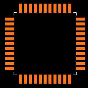
Footprint

3D Model

PIC18F4520 Features

(1) Power Management Features

• Run: CPU on, Peripherals on

• Idle: CPU off, Peripherals on

• Sleep: CPU off, Peripherals off

• Ultra Low 50nA Input Leakage

• Run mode Currents Down to 11 μA Typical

• Idle mode Currents Down to 2.5 μA Typical

• Sleep mode Current Down to 100 nA Typical

• Timer1 Oscillator: 900 nA, 32 kHz, 2V

• Watchdog Timer: 1.4 μA, 2V Typical

• Two-Speed Oscillator Start-up

(2) Flexible Oscillator Structure

• Four Crystal modes, up to 40 MHz

• 4x Phase Lock Loop (PLL) – Available for Crystal and Internal Oscillators

• Two External RC modes, up to 4 MHz

• Two External Clock modes, up to 40 MHz

• Internal Oscillator Block:

- Fast wake from Sleep and Idle, 1 μs typical

- 8 use-selectable frequencies, from 31 kHz to 8 MHz

- Provides a complete range of clock speeds from 31 kHz to 32 MHz when used with PLL

- User-tunable to compensate for frequency drift

• Secondary Oscillator using Timer1 @ 32 kHz

• Fail-Safe Clock Monitor:

- Allows for safe shutdown if peripheral clock stops

(3) Peripheral Highlights

• High-Current Sink/Source 25 mA/25 mA

• Three Programmable External Interrupts

• Four Input Change Interrupts

• Up to 2 Capture/Compare/PWM (CCP) modules, one with Auto-Shutdown (28-pin devices)

• Enhanced Capture/Compare/PWM (ECCP) module (40/44-pin devices only):

- One, two or four PWM outputs

- Selectable polarity

- Programmable dead time

- Auto-shutdown and auto-restart Peripheral Highlights (Continued):

• Master Synchronous Serial Port (MSSP) module Supporting 3-Wire SPI (all 4 modes) and I2C™ Master and Slave modes

• Enhanced Addressable USART module:

- Supports RS-485, RS-232 and LIN/J2602

- RS-232 operation using internal oscillator block (no external crystal required)

- Auto-wake-up on Start bit

- Auto-Baud Detect

• 10-Bit, up to 13-Channel Analog-to-Digital (A/D) Converter module:

- Auto-acquisition capability

- Conversion available during Sleep

• Dual Analog Comparators with Input Multiplexing

• Programmable 16-Level High/Low-Voltage Detection (HLVD) module:

- Supports interrupt on High/Low-Voltage Detection

(4) Special Microcontroller Features

• C Compiler Optimized Architecture

- Optional extended instruction set designed to optimize re-entrant code

• 100,000 Erase/Write Cycle Enhanced Flash Program Memory Typical

• 1,000,000 Erase/Write Cycle Data EEPROM Memory Typical

• Flash/Data EEPROM Retention: 100 Years Typical

• Self-Programmable under Software Control

• Priority Levels for Interrupts

• 8 x 8 Single-Cycle Hardware Multiplier

• Extended Watchdog Timer (WDT)

- Programmable period from 4 ms to 131s

• Single-Supply 5V In-Circuit Serial Programming™ (ICSP™) via Two Pins

• In-Circuit Debug (ICD) via Two Pins

• Wide Operating Voltage Range: 2.0V to 5.5V

• Programmable Brown-out Reset (BOR) with Software Enable Option

Specifications

PIC18F4520-I/PT Tech Specifications

Microchip Technology PIC18F4520-I/PT technical specifications, attributes, parameters and parts with similar specifications to Microchip Technology PIC18F4520-I/PT.

Product Attribute Attribute Value
Factory Lead Time7 Weeks
Package / Case44-TQFP
Mounting TypeSurface Mount
MountSurface Mount
Number of Pins44Pins
Watchdog TimersYes
Number of I/Os36I/Os
Data ConvertersA/D 13x10b
Published2016
SeriesPIC® 18F
PackagingTray
Operating Temperature-40°C~85°C TA
JESD-609 Codee3
Pbfree Codeyes
Part StatusActive
Moisture Sensitivity Level (MSL)3 (168 Hours)
Number of Terminations44Terminations
Terminal FinishMatte Tin (Sn)
Max Power Dissipation1W
Terminal PositionQUAD
Terminal FormGULL WING
Peak Reflow Temperature (Cel)260
Product Attribute Attribute Value
Supply Voltage5V
Frequency40MHz
Time@Peak Reflow Temperature-Max (s)40
Base Part NumberPIC18F4520
Pin Count44
Lead Pitch500μm
Power Supplies5V
InterfaceI2C, SPI, UART, USART
Memory Size32kB
Oscillator TypeInternal
Nominal Supply Current1.1mA
RAM Size1.5K x 8
Voltage - Supply (Vcc/Vdd)4.2V~5.5V
uPs/uCs/Peripheral ICs TypeMICROCONTROLLER, RISC
Number of Bits8Bits
Core ProcessorPIC
PeripheralsBrown-out Detect/Reset, HLVD, POR, PWM, WDT
Program Memory TypeFLASH
Core Size8-Bit
Program Memory Size32KB 16K x 16
ConnectivityI2C, SPI, UART/USART
Bit Size8
Product Attribute Attribute Value
Access Time40 μs
Has ADCYES
DMA ChannelsNO
Data Rate10 Mbps
Data Bus Width8b
Number of Timers/Counters4Timers/Counters
Address Bus Width8b
Density256 kb
EEPROM Size256 x 8
CPU FamilyPIC
Number of A/D Converters1A/D Converter
Number of ADC Channels13ADC Channels
Number of PWM Channels5PWM Channels
Width10mm
Length10mm
Height1.05mm
RoHS StatusROHS3 Compliant
Radiation HardeningNo
REACH SVHCNo SVHC
Lead FreeLead Free
0 Products View Similar

PIC18F4520 Functional Block Diagram

Functional Block Diagram

PIC18F4520 Alternatives

• PIC18F4520 is widely used in home and industrial automation

• Student projects for motor controlling and sensor interfacing

• GPS and security systems

• Gas sensor projects

• Production of temperature data logger

• Serial Communication

• Central heating projects

• Embedded system

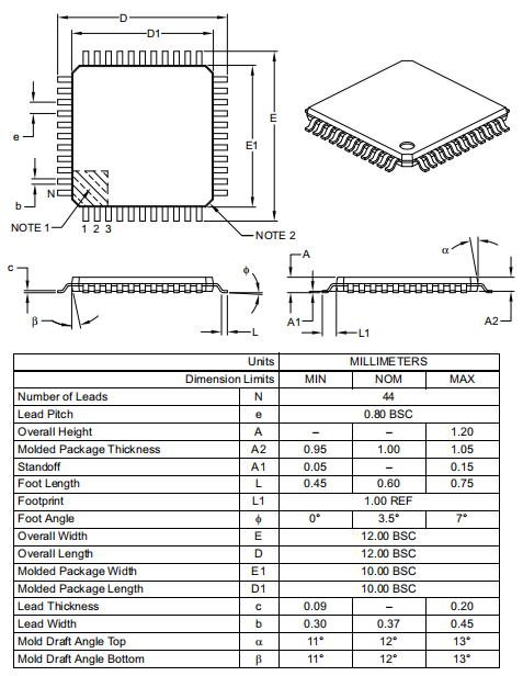
PIC18F4520 Package

Package

PIC18F4520 Manufacturer

Microchip Technology Incorporated is a leading manufacturer of smart, networked, and secure embedded control solutions. Customers may create optimal designs using the company's simple development tools and broad product choices, which reduce risk while lowering overall system costs and time to market. The company's technologies are used by over 120,000 clients in the industrial, automotive, consumer, aerospace and defense, communications, and computing sectors. Microchip, based in Chandler, Arizona, offers outstanding technical support as well as dependable delivery and quality.

Datasheet PDF

PIC18F4520-I/PT Documents

Download datasheets and manufacturer documentation for PIC18F4520-I/PT

Frequently Asked Questions

1.What is the difference between MCU PIC18F452 and PIC18F4520?
(1)The difference between the single-chip microcomputer PIC18F452 and PIC18F4520 is that one has a USB, the other does not. (2) Microcontrollers are a kind of integrated circuit chip, which uses VLSI technology to integrate the central processing unit CPU with data processing capabilities, random access memory RAM, read-only memory ROM, various I/O ports and interrupt systems, timer/counter and other functions (may also include display drive circuit, pulse width modulation circuit, analog multiplexer, A/D converter and other circuits) are integrated on a silicon chip to form a small and complete microcomputer system, It is widely used in the field of industrial control. From the 1980s, from the then 4-bit and 8-bit single-chip microcomputers to the current 300M high-speed single-chip microcomputer.
2.How does the PIC18F4520 microcontroller adjust the PWM speed of the DC brushless motor?
The output PWM signal of the single-chip microcomputer can not be directly added to the switch tube, and the turn-on and the cut-off voltage value of the tube must be achieved through signal amplification. The single-chip microcomputer controls the switching tube to turn on and off after amplifying the PWM signal output by the program, thereby obtaining a large voltage and high current PWM signal formed by the switching tube. The sine signal can be simulated into sine wave signals of different frequencies to control the motor speed.
3.What is the difference between PIC18F4550 and PIC18F4520?
One with USB, the other does not.
FAQ
1.What is the difference between MCU PIC18F452 and PIC18F4520?
(1)The difference between the single-chip microcomputer PIC18F452 and PIC18F4520 is that one has a USB, the other does not. (2) Microcontrollers are a kind of integrated circuit chip, which uses VLSI technology to integrate the central processing unit CPU with data processing capabilities, random access memory RAM, read-only memory ROM, various I/O ports and interrupt systems, timer/counter and other functions (may also include display drive circuit, pulse width modulation circuit, analog multiplexer, A/D converter and other circuits) are integrated on a silicon chip to form a small and complete microcomputer system, It is widely used in the field of industrial control. From the 1980s, from the then 4-bit and 8-bit single-chip microcomputers to the current 300M high-speed single-chip microcomputer.
2.How does the PIC18F4520 microcontroller adjust the PWM speed of the DC brushless motor?
The output PWM signal of the single-chip microcomputer can not be directly added to the switch tube, and the turn-on and the cut-off voltage value of the tube must be achieved through signal amplification. The single-chip microcomputer controls the switching tube to turn on and off after amplifying the PWM signal output by the program, thereby obtaining a large voltage and high current PWM signal formed by the switching tube. The sine signal can be simulated into sine wave signals of different frequencies to control the motor speed.
3.What is the difference between PIC18F4550 and PIC18F4520?
One with USB, the other does not.

TAGS

Share