L293D Motor Driver Working
The L293DNE is a PTH quadruple, high-current, half-H driver IC. Today, Magi will tell you some details about L293DNE.

The L293DNE is a PTH quadruple, high-current, half-H driver IC. Today, Magi will tell you some details about L293DNE.
1230
Apr 15, 2022
Hubery Dick
L293D Motor Driver Working
The L293DNE is a PTH quadruple, high-current, half-H driver IC. Today, Magi will tell you some details about L293DNE.
L293DNE
| Quantity | Unit Price | Ext. Price |
|---|---|---|
| 1+ | $4.85275 | $4.85 |
| 10+ | $4.57807 | $45.78 |
| 100+ | $4.31893 | $431.89 |
| 500+ | $4.07446 | $2037.23 |
| 1000+ | $3.84383 | $3843.83 |
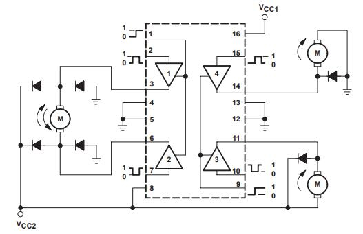
The L293DNE is a triple half-H driver with a high current output. At voltages ranging from 4.5V to 36V, the L293DNE is designed to generate bidirectional driving currents of up to 600mA.
In positive supply applications, the device is designed to drive inductive loads like relays, solenoids, dc, and bipolar stepping motors, as well as another high current/high voltage loads. TTL compatibility is present on all inputs.
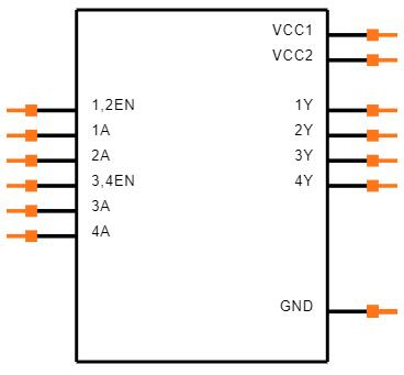
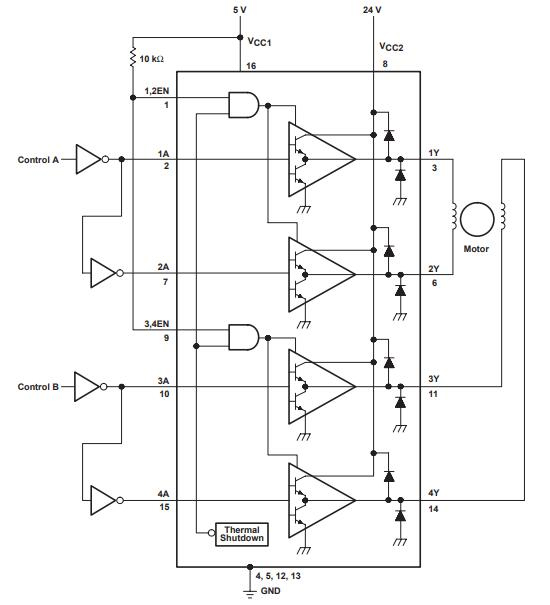
Each output has a Darlington transistor sink and a pseudo-Darlington source, making it a complete totem-pole drive circuit. Drivers are enabled in pairs, with 1,2EN enabling drivers 1 and 2 and 3,4EN enabling drivers 3 and 4.
The linked drivers are activated when the enable input is high, and their outputs are active and in phase with their inputs. Those drivers are disabled and their outputs are off and in the high impedance state when the enable input is low. Each pair of drivers comprises a full-H (or bridge) reversible drive ideal for solenoid or motor applications with the necessary data inputs.
Symbol
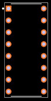
Footprint
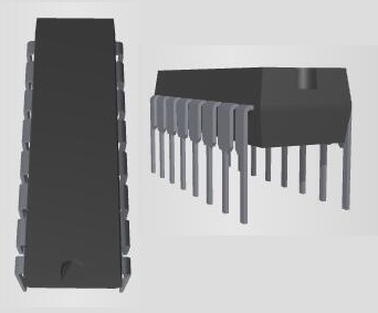
3D Models
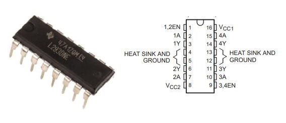
Separate Input logic Supply
Internal ESD Protection
Thermal Shutdown
High noise immunity inputs
Output current 600mA per channel
Output clamp diodes for inductive transient suppression
Texas Instruments L293DNE technical specifications, attributes, parameters and parts with similar specifications to Texas Instruments L293DNE.
| Product Attribute | Attribute Value | |
|---|---|---|
| Lifecycle Status | ACTIVE (Last Updated: 3 days ago) | |
| Factory Lead Time | 6 Weeks | |
| Mount | Surface Mount | |
| Mounting Type | Through Hole | |
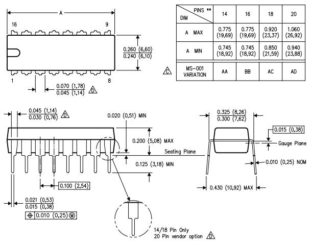
| Package / Case | 16-DIP (0.300, 7.62mm) | |
| Number of Pins | 16Pins | |
| Weight | 670.01263mg | |
| Voltage Rated | 20V | |
| Operating Temperature | 0°C~70°C TA | |
| Packaging | Tube | |
| Tolerance | 10% | |
| JESD-609 Code | e4 | |
| Pbfree Code | yes | |
| Part Status | Active | |
| Moisture Sensitivity Level (MSL) | 1 (Unlimited) | |
| Number of Terminations | 16Terminations | |
| ECCN Code | EAR99 | |
| Resistance | 800mOhm |
| Product Attribute | Attribute Value | |
|---|---|---|
| Terminal Finish | Nickel/Palladium/Gold (Ni/Pd/Au) | |
| Applications | General Purpose | |
| Capacitance | 22μF | |
| Voltage - Rated DC | 20V | |
| Voltage - Supply | 4.5V~36V | |
| Terminal Position | DUAL | |
| Supply Voltage | 5V | |
| Base Part Number | L293 | |
| Function | Driver - Fully Integrated, Control and Power Stage | |
| Number of Outputs | 4Outputs | |
| Case Code (Metric) | 7343 | |
| Case Code (Imperial) | 2917 | |
| Output Voltage | 36V | |
| ESR (Equivalent Series Resistance) | 800mOhm | |
| Interface | Parallel | |
| Operating Supply Current | 24mA | |
| Output Configuration | Half Bridge (4) | |
| Logic Function | AND |
| Product Attribute | Attribute Value | |
|---|---|---|
| Output Polarity | TRUE | |
| Voltage - Load | 4.5V~36V | |
| Driver Number of Bits | 4Bits | |
| Output Peak Current Limit-Nom | 1.2A | |
| Supply Voltage1-Nom | 24V | |
| Turn Off Time | 0.8 µs | |
| Built-in Protections | TRANSIENT; THERMAL | |
| Motor Type - AC, DC | Brushed DC | |
| Motor Type - Stepper | Bipolar | |
| Height | 5.08mm | |
| Length | 19.8mm | |
| Width | 6.35mm | |
| Thickness | 4.57mm | |
| REACH SVHC | No SVHC | |
| Radiation Hardening | No | |
| RoHS Status | ROHS3 Compliant | |
| Lead Free | Lead Free |
1. Stepper Motor Drivers
2. DC Motor Drivers
3. Latching Relay Drivers

Texas Instruments Inc. (TI) is an American technology company that designs and manufactures semiconductors and various integrated circuits, which it sells to electronics designers and manufacturers globally. Its headquarters are in Dallas, Texas, United States. TI is one of the top ten semiconductor companies worldwide, based on sales volume. Texas Instruments's focus is on developing analog chips and embedded processors, which account for more than 80% of its revenue. TI also produces TI digital light processing (DLP) technology and education technology products including calculators, microcontrollers, and multi-core processors.
The differences between L293D and L298N are following:
1. L293D Drivers Operate at 4.5V to 36V whereas L298N can be Operates at up to 46V.
2. Maximum 600mA Current can be drawn through both channels of L293D whereas L298N Motor Driver can draw up to 2A from both channels.
3. L293 is a quadruple motor driver that uses a half-H driver while L298 is a dual full-H driver, i.e, in L293 all four input-output lines are independent while in L298, a half-H driver cannot be used independently, only a full H driver has to be used.
4. As L293 output current for each channel is 650mA whereas it is 2A for L298. Hence, the heat sink is provided in L298 motor drivers.
5. EMFs are provided internally in L293D but must be provided externally in L298.
6. L293D is suitable for small current drawing motors like BO motor, DC geared motors up to 500 RPM, and small stepper motors which take less current up to 600mA at their highest torque rating. Whereas L298N has the advantage of higher output current up to 2A and therefore it is suitable for high torque and high RPM motors like Johnson motors and high torque DC Geared motors.
Download datasheets and manufacturer documentation for L293DNE
TAGS
Comments