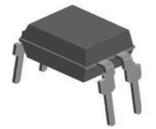
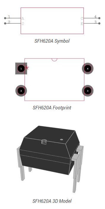
The schematic given below is a switching circuit using SFH620A Optocoupler.
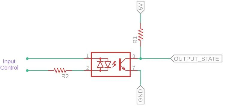
SFH620A Schematic
The input is applied to the LEDs, which are the initial portion of the optocoupler. To limit the current through the LEDs, a resistor is connected in series with them. The phototransistor gain is controlled by the intensity of the infrared light emitted by them, which is controlled by the current. The higher the phototransistor gain, the lower the limiting resistance value. The phototransistor component receives the load. This is where the swapping begins.
If the phototransistor detects enough infrared energy to turn it, electricity will flow from the emitter to the collector. However, because the phototransistor is linked to a pull-up resistor, the output state will be low, i.e. 5 volts will be stepped down to 0 and an LED attached as a load will not glow. If the phototransistor detects no radiation, it conducts no current and the output state is high. Let's imagine there's an LED attached to the output state, which will light up.