ATTENTION: Due to increased demand and order volume, processing time may take an additional 1-3 business days.
HomeCommunitySubjectSN74LS47N Decoder/Driver: Features, Pinout, and Datasheet

SN74LS47N Decoder/Driver: Features, Pinout, and Datasheet

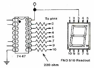
SEVEN SEGMENT DECODER/DRIVER The SN74LS47N is a Low Power Schottky BCD to 7-Segment Decoder/Drivers feature active-low outputs, designed for driving, common-anode LEDs or incandescent indicators directly. This article mainly introduces features, pinout, datasheet and other detailed information about Rochester Electronics, LLC SN74LS47N.

362

Oct 3, 2021

Vicky Dillon

Tutorial | Using the 7447 74HC47 BCD to 7 Segment Display Decoder


SEVEN SEGMENT DECODER/DRIVER

The SN74LS47N is a Low Power Schottky BCD to 7-Segment Decoder/Drivers feature active-low outputs, designed for driving, common-anode LEDs or incandescent indicators directly. This article mainly introduces features, pinout, datasheet and other detailed information about Rochester Electronics, LLC SN74LS47N.

SN74LS47N

Inquiry
Min.: 1 Mult.: 1
Price not displayed? Not available to buy online? Please send an RFQ, and we will respond immediately.
Quick Links

SN74LS47N Description

The SN74LS47N is a Low Power Schottky BCD to 7-Segment Decoder/Drivers feature active-low outputs, designed for driving, common-anode LEDs or incandescent indicators directly. The IC for driving lamp buffers or common-cathode LEDs. All of the circuits except LS49 have full ripple-blanking input/output controls and a lamp test input. Display patterns for BCD input counts above 9 are unique symbols to authenticate input conditions. Its circuits incorporate automatic leading and/or trailing-edge zero-blanking control (RBI\ and RBO\). Lamp test (LT/) of these types may be performed at any time when the BI\/RBO\ node is at a high level. All types (including the '49 and 'LS49) contain an overriding blanking input (BI\), which can be used to control the lamp intensity by pulsing or to inhibit the outputs. Inputs and outputs are entirely compatible for use with TTL logic outputs.


The circuits accept 4-bit binary-coded-decimal (BCD) and, depending on the state of the auxiliary inputs, decode this data to drive a 7-segment display indicator. The relative positive-logic output levels, as well as conditions required at the auxiliary inputs, are shown in the truth tables. Output configurations of the SN74LS47N are designed to withstand the relatively high voltages required for 7-segment indicators.


These outputs will withstand 15 V with a maximum reverse current of 250μA. Indicator segments requiring up to 24 mA of current may be driven directly from the SN74LS47N high-performance output transistors. Display patterns for BCD input counts above nine are unique symbols to authenticate input conditions.

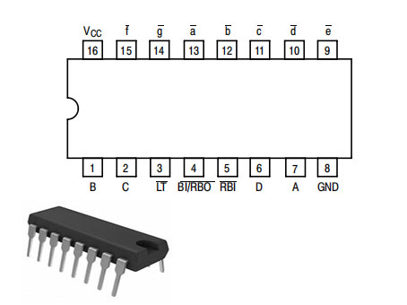
SN74LS47N Pinout

SN74LS47N CAD Model

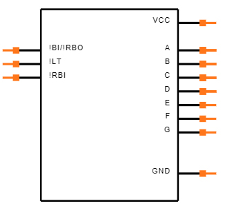
Symbol

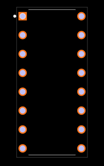
Footprint

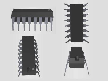
3D Model

SN74LS47N Features

• Lamp Intensity Modulation Capability (BI/RBO)

• Open-collector Outputs Drive Indicators Directly

• Lamp Test Provision

• Leading/Trailing Zero Suppression

• Input Clamp Diodes Limit High-Speed Termination Effects

Specifications

Rochester Electronics, LLC SN74LS47N technical specifications, attributes, parameters and parts with similar specifications to Rochester Electronics, LLC SN74LS47N.

SN74LS47N Tech Specifications

Rochester Electronics, LLC SN74LS47N technical specifications, attributes, parameters and parts with similar specifications to Rochester Electronics, LLC SN74LS47N.

Product Attribute Attribute Value
Mounting TypeThrough Hole
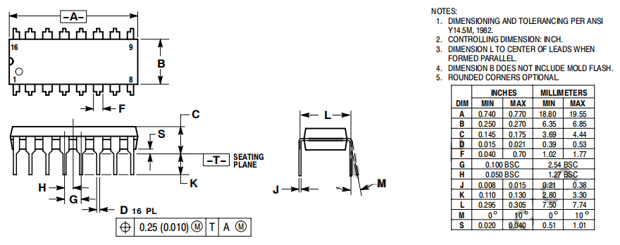
Package / Case16-DIP (0.300, 7.62mm)
Surface MountNO
Operating Temperature0°C~70°C
PackagingTube
JESD-609 Codee4
Pbfree Codeyes
Part StatusObsolete
Moisture Sensitivity Level (MSL)3 (168 Hours)
Number of Terminations16Terminations
ECCN CodeEAR99
Terminal FinishNICKEL PALLADIUM GOLD
HTS Code8542.39.00.01
Product Attribute Attribute Value
Voltage - Supply4.75V~5.25V
Terminal PositionDUAL
Peak Reflow Temperature (Cel)NOT SPECIFIED
Number of Functions1Function
Supply Voltage5V
Terminal Pitch2.54mm
Time@Peak Reflow Temperature-Max (s)NOT SPECIFIED
Pin Count16
JESD-30 CodeR-PDIP-T16
Qualification StatusNot Qualified
Supply Voltage-Max (Vsup)5.25V
Supply Voltage-Min (Vsup)4.75V
Configuration7 Segment
Product Attribute Attribute Value
InterfaceBCD
Current - Supply7mA
FamilyLS
Output PolarityINVERTED
Logic IC TypeSEVEN SEGMENT DECODER/DRIVER
Display TypeLED
Propagation Delay (tpd)100 ns
Input ConditioningSTANDARD
Length19.175mm
Height Seated (Max)4.44mm
Width7.62mm
RoHS StatusNon-RoHS Compliant
0 Products View Similar

SN74LS47N To 7 Segment

SN74LS47N to 7 segment

N74LS47N Alternatives

Part Number Description Manufacturer
7604501EALOGIC BCD-to-Seven-Segment Decoders/Drivers 16-CDIP -55 to 125 Texas Instruments
54LS47/BEAJCLOGIC LS SERIES, SEVEN SEGMENT DECODER/DRIVER, INVERTED OUTPUT, CDIP16, CERDIP-16 Motorola Mobility LLC

SN74LS47N Applications

• Signal Processing

• Aerospace

• Defence

• Military

SN74LS47N Package

Package

SN74LS47N Manufacturer

Rochester Electronics ranks as a global leading semiconductor provider. Due to their products' characteristics of high quality and durability, these products are suitable for long-term production and maintenance in the fields of industry, transportation and high-reliability markets. Their large inventory includes more than 100,000 products and 15 billion units, making them exceed other companies in terms of selection, capabilities, or solutions.

Datasheet PDF

Download datasheets and manufacturer documentation for Rochester Electronics, LLC SN74LS47N.

SN74LS47N Documents

Download datasheets and manufacturer documentation for SN74LS47N

Frequently Asked Questions

1.What should I do if SN74LS47N is not found in P in Proteus?
Select 74LS from P in Proteus, 74LS47 under the 74LS list, SN74LS47N is a dual in-line plastic package, when placing 74LS47, select DIL16 is dual in-line. SN stands for the Texas company chip.
2.What is the difference between SN74LS47N and SN74LS47P?
The N and P at the end of SN74LS47N and SN74LS47P are packages marking symbols, and both N and P are dual-in-line plastic packaging. The National Semiconductor Corporation of the United States and others use the N mark for dual-in-line plastic packaging, and the Motorola Company of the United States uses the P mark for dual-inline plastic packaging. Different manufacturers, the same chip.
3.How to use SN74LS47N in mulitisim to light up the digital tube?
In fact, this chip is not needed, because the general digital tube that can display 0 to 9 has only 4 input terminals. If you want to light up the digital tube, you only need to connect these four input terminals. But it should be noted that from left to right are Q3, Q2, Q1, and Q0.
FAQ
1.What should I do if SN74LS47N is not found in P in Proteus?
Select 74LS from P in Proteus, 74LS47 under the 74LS list, SN74LS47N is a dual in-line plastic package, when placing 74LS47, select DIL16 is dual in-line. SN stands for the Texas company chip.
2.What is the difference between SN74LS47N and SN74LS47P?
The N and P at the end of SN74LS47N and SN74LS47P are packages marking symbols, and both N and P are dual-in-line plastic packaging. The National Semiconductor Corporation of the United States and others use the N mark for dual-in-line plastic packaging, and the Motorola Company of the United States uses the P mark for dual-inline plastic packaging. Different manufacturers, the same chip.
3.How to use SN74LS47N in mulitisim to light up the digital tube?
In fact, this chip is not needed, because the general digital tube that can display 0 to 9 has only 4 input terminals. If you want to light up the digital tube, you only need to connect these four input terminals. But it should be noted that from left to right are Q3, Q2, Q1, and Q0.

TAGS

Share