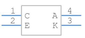
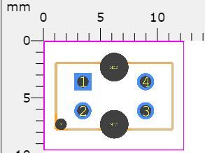
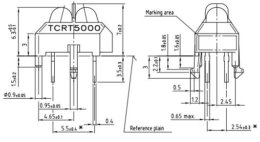
The IR sensor circuit for the TCRT500 is given below. The IR sensor in this circuit consists of a photodiode and a phototransistor, which act as a transmitter and receiver, respectively.
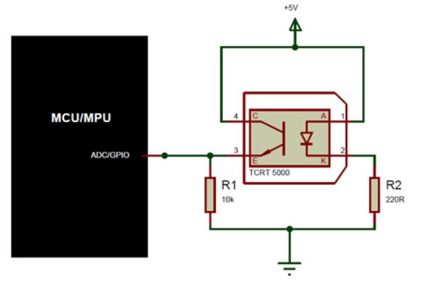
TCRT500 Circuit
A 220R resistor is used to activate the photodiode, while a 10K resistor is used to link the phototransistor to GND. Because the transistor biasing is mostly controlled by the received IR light, the transistor in the circuit does not have a base pin. As a result, the photodiode's infrared light strikes a target and returns to the phototransistor to bias it.
Depending on the application, this IR sensor can be utilized as an analog or digital sensor. The main disadvantages of this sensor are that they are easily affected by environmental variables.
It will not only respond to infrared light utilizing the photodiode, but it will also respond to infrared light from many light sources that are generally available, similar to the phototransistor.
Noise cancellation is usually used within the application to solve this problem. So, using an MCU or MPU's GPIO pin, we can deactivate the photodiode and then verify how much noise the transistor in the sensor is reading before activating the photodiode to calculate the change in values by invalidating the noise present while the photodiode was deactivated.