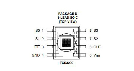
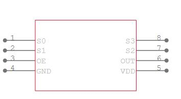
This Arduino compatible TCS3200 colour sensor module consists of a TAOS TCS3200 RGB sensor chip and 4 white LEDs. The main part of the module is the TCS3200 chip which is a Color Light-to-Frequency Converter.
With the help of a microprocessor, the TCS3200 colour sensor module can detect colours. The output frequency from the 6th pin is really measured by the microcontroller.
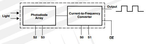
When each filter is activated, we must measure the frequency from the 6th pin to determine the colour of an object.
Set both S2 and S3 to LOW and take a frequency reading. Now we get the object's RED component's intensity.
To get the intensity of the BLUE component in the object, set S2 to LOW and S3 to HIGH.
Set both S2 and S3 to HIGH to determine the object's GREEN component's intensity.
To determine the true colour of the object, compare the frequencies of the three components.
TIP: In Arduino, we can use the ‘pulseIn’ command to get the frequency variations.
e.g.:
digitalWrite(S2, LOW);digitalWrite(S3, LOW);   //Activating photodiode with red filter
red = pulseIn(outpin, LOW);
The value corresponding to the red color component of the object color is obtained here.
Similarly, we must change the S2 and S3 states of each photodiode and read the appropriate values of the green and blue color components of the object color.
We get an estimated value of red=16, green=53, and blue=45 for a Red item. Ambient light and experiment setting may influence this. It is preferable to shield the item and sensor from ambient light for the best results.