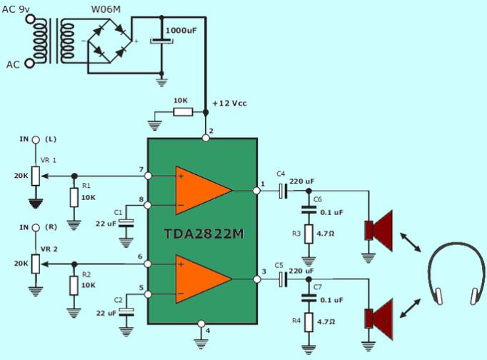
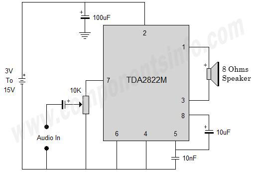
TDA2822M Amplifier Test Circuit in Stereo Mode
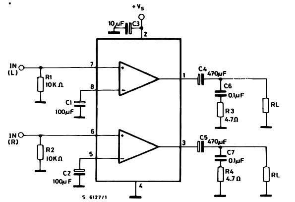
Test Circuit in Stereo Mode
The left channel input is connected to the first built-in amplifier's non-inverting input (pin 1), while the right channel is connected to the second built-in amplifier's non-inverting input (pin 16). Separate 1000uF capacitors are used to link the inverting input of these built-in amplifiers to the ground (C5 and C6). Pins 6 and 11 of the IC control the amplified outputs (left and right). Capacitors C1 and C2 are used to connect the outputs to the matching speakers. The resistor-capacitor branch connected between speakers (0.1uF and 4.7 ohm) is intended to improve high-frequency stability and prevent oscillations. C7 is the power supply filter capacitor.
TDA2822M Amplifier Test Circuit in Bridge Mode
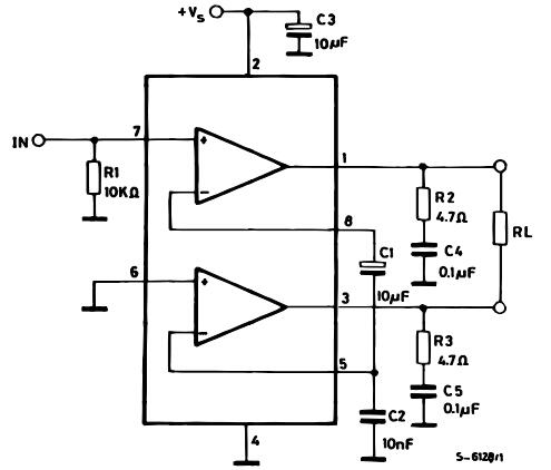
Test Circuit in Bridge Mode
The output power of the TDA2822M amplifier can be boosted by employing the bridge configuration in mono mode, as shown in Figure 2. The audio signal is fed into the first built-in amplifier's non-inverting input. The second built-in amplifier's non-inverting input is grounded. The C9, C11 capacitor branch grounds the inverting input of these amplifiers. The R5, C8, and R6, C10 branches are intended to improve high-frequency stability and reduce oscillations. C12 is a capacitor that filters the power source.