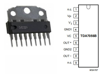
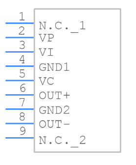
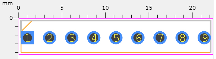
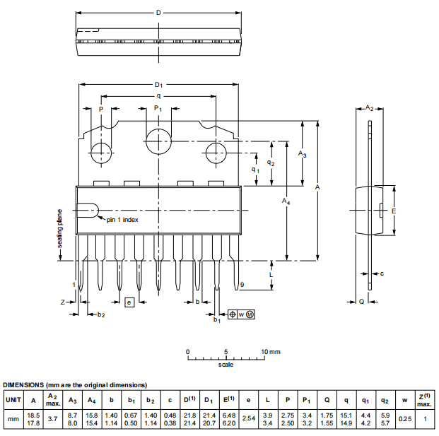
TDA7056A and TDA7056B are two TDA7056 variations that are now more widely available. Although their performance and pinout are quite similar, they will not function in the same circuit.
TDA7056B appears to be the better of the two, with output power somewhat higher than 16 ohms and, this time, a reference power output of 5.5W for an 8-ohm speaker on the datasheet. Because it appears to be the best, this is the only chip I brought and tested.
TDA7056A/TDA7056B require at least two additional components than TDA7056. This is due to the fact that a DC volume control input must be grounded via a 1F capacitor. TDA7056A/TDA7056B (as opposed to TDA7056) have a DC offset on their input pins, which necessitates the use of a 470nF capacitor in series with the input and input pins.
As a result, there are drawbacks such as the requirement for additional components and larger circuit boards. The advantage is that we have more flexibility with the DC volume control pin 5 than with the basic TDA7056:
This dedicated pin can now be used to connect the volume control potentiometer.
A logarithmic potentiometer is more accurate than a logarithmic volume control input. This enables volume control with ordinary linear potentiometers.
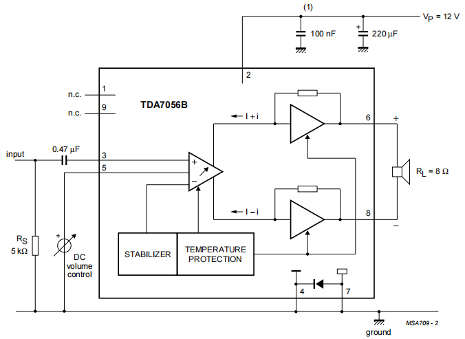
After adjustments, this is a schematic diagram of a simple amplifier. TDA7056A has a reasonable maximum gain of around 27dB, while TDA7056B has a reasonable maximum gain of 32dB.
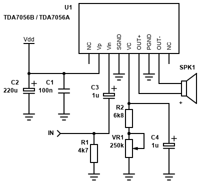
Simplified Schematic
Like TDA7056, power supply bypass capacitors: C1 and C2 are required. C1 should be 100nF ceramic and be as close as possible to the TDA7056B pin. C2 is an electrolytic capacitor of 220μF or higher. Electrolytic capacitors are polarized, so the positive lead must enter a positive voltage source. If the capacitor is new, this is the longest lead, but check the case anyway, because the negative lead is usually clearly marked.
C3 is the input capacitance. It is recommended in the data sheet to use 470nF, combined with 20k input impedance, which will provide a high-pass cutoff frequency of 16.93Hz-calculated by 1/(2πRC)-1/(2 × 3.14159 × 20000 × 0.00000047).
C3 should be polyester or electrolytic capacitor. As we all know, polyester fiber has the best audio quality, but on an amplifier of this size, you are unlikely to notice the difference, and electrolyte is fine. Avoid using ceramic capacitors. If you have 1µF electrolyte, please feel free to use them (this is what I did on the circuit board). The positive lead must face the chip.
R1 provides a grounded DC path for the audio signal and a predictable input impedance for the amplifier, suitable for any source you connect. The resistor is suggested to be 5k in the data sheet, but 4.7k is the more commonly available value and will work properly.