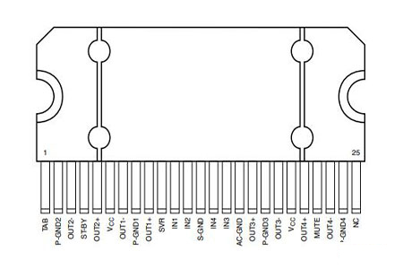
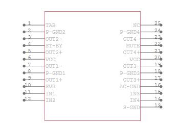
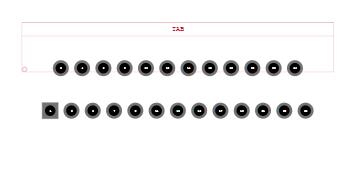
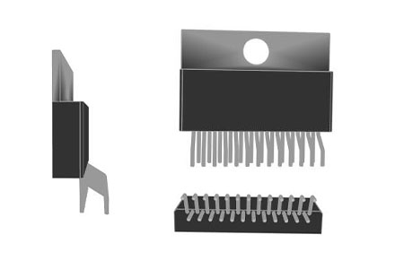
TDA7388 has demonstrated the circuit below. It's a four-channel amplifier, to be precise. As a result, as shown in the diagram below, we can connect four speakers to this amplifier.
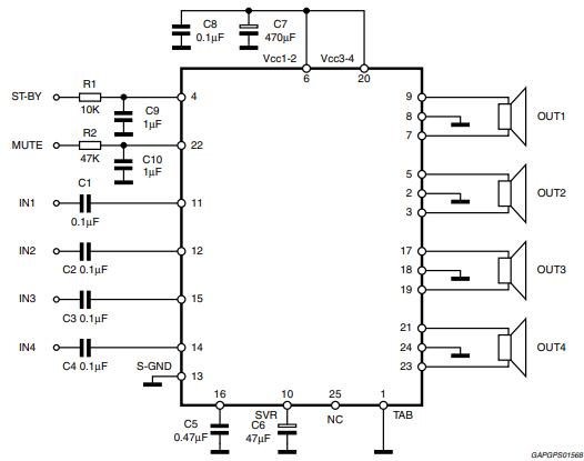
TDA7388 Standard Test and Application Circuit
The SVR capacitor controls the turn ON/OFF sequence and is utilized for ripple rejection. The minimum recommended value of an SVR capacitor for this application is 10 F. Pin 10 is used to connect SVR capacitors. There are two modes on the TDA7388: standby and silent. By connecting directly to Vs, these modes can be used immediately. In the lack of real CMOS ports and microprocessors, conventional/low-power transistors can be used to operate the Muting and Standby pins. RC cells are utilized in the circuit to smooth out transitions and prevent audio noise.
Pin 22 controls the mute function. A 10 A current will pass through this pin under normal conditions. As a result, we can connect up to 70 k of muting-series resistance (R2). This resistance is high enough to allow a muting capacitor to be as little as 1F. If this resistance is higher than the recommended amount, the voltage across pin 22 exceeds the 1.5 V threshold value, preventing the mute line from turning off.
The time constant is assigned to a stand-by pin that is slower than 2.5 V/ms in order to provide a pop-free transition.