LED Lights reacting with Music - TIP31C TRANSISTOR - KeLaMan Production
Trans GP BJT NPN 100V 3A 3-Pin(3 Tab) TO-220 Tube
The TIP31C is a bipolar power transistor which designed for use in general purpose amplifier and switching applications.

Trans GP BJT NPN 100V 3A 3-Pin(3+Tab) TO-220 Tube The TIP31C is a bipolar power transistor which designed for use in general purpose amplifier and switching applications.
523
Jun 24, 2021
Ralap Trollpoe
LED Lights reacting with Music - TIP31C TRANSISTOR - KeLaMan Production
Trans GP BJT NPN 100V 3A 3-Pin(3 Tab) TO-220 Tube
The TIP31C is a bipolar power transistor which designed for use in general purpose amplifier and switching applications.
TIP31C
| Quantity | Unit Price | Ext. Price |
|---|---|---|
| 1+ | $1.09721 | $1.1 |
| 10+ | $1.03511 | $10.35 |
| 100+ | $0.97652 | $97.65 |
| 500+ | $0.92124 | $460.62 |
| 1000+ | $0.8691 | $869.1 |
The TIP31C is a base island technology NPN power transistor in TO-220 plastic package with better performances than the industry standard TIP31C that make this device suitable for audio, power linear and switching applications. The PNP type is TIP32C.

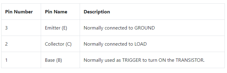
Symbol

Footprint

3D Model

New enhanced series
High switching speed
hFE improved linearity
hFE Grouping
STMicroelectronics TIP31C technical specifications, attributes, parameters and parts with similar specifications to STMicroelectronics TIP31C.
STMicroelectronics TIP31C technical specifications, attributes, parameters and parts with similar specifications to STMicroelectronics TIP31C.
| Product Attribute | Attribute Value | |
|---|---|---|
| Lifecycle Status | ACTIVE (Last Updated: 8 months ago) | |
| Factory Lead Time | 8 Weeks | |
| Contact Plating | Tin | |
| Mount | Through Hole | |
| Mounting Type | Through Hole | |
| Package / Case | TO-220-3 | |
| Number of Pins | 3Pins | |
| Weight | 4.535924g | |
| Transistor Element Material | SILICON | |
| Collector-Emitter Breakdown Voltage | 100V | |
| Collector-Emitter Saturation Voltage | 1.2V | |
| Frequency - Gain Bandwidth Product (GBP) | 3MHz | |
| Power Dissipation (Max) | 2W | |
| Number of Elements | 1 Element | |
| hFEMin | 10 | |
| Operating Temperature | 150°C TJ |
| Product Attribute | Attribute Value | |
|---|---|---|
| Packaging | Tube | |
| JESD-609 Code | e3 | |
| Part Status | Active | |
| Moisture Sensitivity Level (MSL) | 1 (Unlimited) | |
| Number of Terminations | 3Terminations | |
| ECCN Code | EAR99 | |
| Voltage - Rated DC | 100V | |
| Current Rating | 3A | |
| Base Part Number | TIP31 | |
| Element Configuration | Single | |
| Power Dissipation | 2W | |
| Transistor Application | SWITCHING | |
| Polarity/Channel Type | NPN | |
| Transistor Type | NPN | |
| Collector Emitter Voltage (VCEO) | 100V | |
| Max Collector Current | 3A |
| Product Attribute | Attribute Value | |
|---|---|---|
| DC Current Gain (hFE) (Min) @ Ic, Vce | 10 @ 3A 4V | |
| Current - Collector Cutoff (Max) | 300μA | |
| JEDEC-95 Code | TO-220AB | |
| Vce Saturation (Max) @ Ib, Ic | 1.2V @ 375mA, 3A | |
| Transition Frequency | 3MHz | |
| Collector Base Voltage (VCBO) | 100V | |
| Emitter Base Voltage (VEBO) | 5V | |
| Max Junction Temperature (Tj) | 150°C | |
| Height | 19.68mm | |
| Length | 10.4mm | |
| Width | 4.6mm | |
| REACH SVHC | No SVHC | |
| Radiation Hardening | No | |
| RoHS Status | ROHS3 Compliant | |
| Lead Free | Lead Free |
When you want a simple switching device for medium power loads. TIP31C is one of the basic transistors that are cheap and easily available. With electrical characteristics suiting many applications it is fairly popular. So the component is best suited when choosing a random switching device.
When you want to amplify a signal. The amplifying factor of TIP31C is fairly good and the important thing is that its gain is almost linear. So these characteristics make TIP31C one of best contender for amplifying applications.
TIP31C can be controlled by microcontroller pulses because of its gain and high speed response. So it can be used in high speed switching applications.
DC motor speed control
Lighting systems
PWM applications
Relay drivers
Switch mode power supply
Audio Amplifiers
Signal Amplifiers
STMicroelectronics is a global independent semiconductor company and is a leader in developing and delivering semiconductor solutions across the spectrum of microelectronics applications. An unrivaled combination of silicon and system expertise, manufacturing strength, Intellectual Property (IP) portfolio and strategic partners positions the Company at the forefront of System-on-Chip (SoC) technology and its products play a key role in enabling today's convergence trends.
TIP31C can be used like any other power transistor. Here we are going to use it in common emitter configuration.
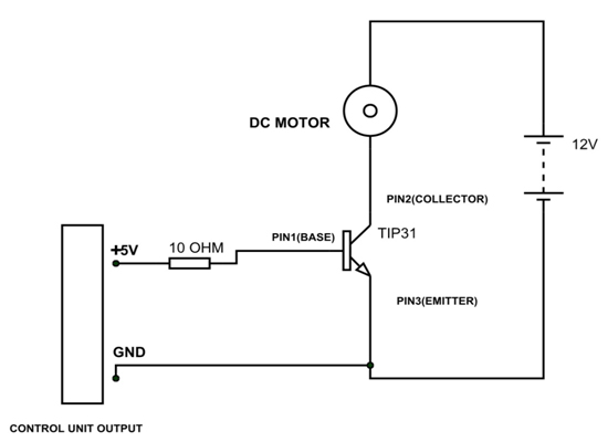
In the circuit above, TIP31C is used as a simple switching device, and a small DC motor is used as the load. The trigger for turning on the transistor is provided by the control unit (not microcontroller, because microcontroller cannot deliver 300mA). The control unit provides +5V pulses to base of transistor. The control unit ground must be connected to transistor emitter compulsorily.
The 10Ω resistor is provided for limiting the current through base. This base current limiting resistor is important and can be chosen accurately by calculating:
Maximum current through BASE = 1 Amp
Choose BASE current = 0.9 Amp
Maximum Voltage across BASE and EMITTER= 5 Volt
Choose Vbe = 4.5
Voltage across resistor R = CONTROL UNIT VOLTAGE OUTPUT – 4.5 = XX V
Resistor R = XX/0.9 = YYΩ.
Put YY Ω resistance in series with base as shown in circuit
Under normal conditions the transistor will be off as these will be no base current. When the control unit voltage pulses reaches base then current flows through base of transistor. With base current flow, transistor gets turned on. With that there will be collector current which flows through motor. So the motor rotates. The motor will be keep rotating until there will be base current.
When the control unit output goes low the base current becomes zero. The transistor gets turned off when the base current becomes zero. So the collector current also becomes zero, bringing motor to stop.
This way we can use TIP31C as a switching device. The circuit used above is a simple testing circuit and is not an application circuit. Using it without arrangements like HEAK SINK, FLYBACK DIODE etc, will damage the device.
For using the TIP31C as an amplifier one needs to consider current gain characteristics. So we will introduce the current gain graph of TIP31C for better understanding. The typical DC GAIN graph of TIP31C is given below.
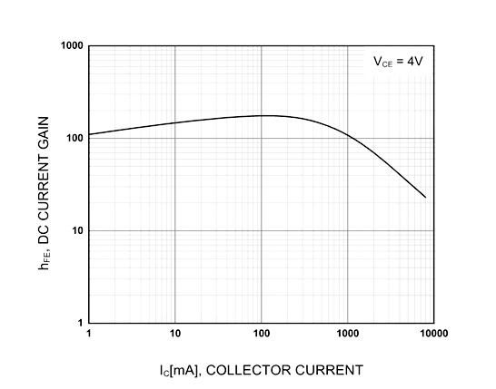
From the graph above, the gain is almost 100 when collector current is 1000mA or 1A. And gain drops to 60 when collector current is 2000mA or 2A. When collector current goes beyond 2A, the gain is almost linear. This parameter value is important for amplifiers. By taking these ranges into consideration we can make appropriate arrangements for better performance.
Download datasheets and manufacturer documentation for STMicroelectronics TIP31C.
Download datasheets and manufacturer documentation for TIP31C
TAGS
Comments