ATTENTION: Due to increased demand and order volume, processing time may take an additional 1-3 business days.
HomeCommunitySubjectTJA1050 High-speed Can Transceiver: Datasheet, TJA1050 vs. MCP2551

TJA1050 High-speed Can Transceiver: Datasheet, TJA1050 vs. MCP2551

Interface - Drivers, Receivers, Transceivers 8-SOIC (0.154, 3.90mm Width) 4.75V~5.25V -40°C~150°C TJA1050 1.27mm 5V IC TXRX CAN 8BIT 5.25V SOT96-1

321

Oct 30, 2021

Archer Meg

Raspberry Pi: Configuration of MCP2515 and TJA1050

terface - Drivers, Receivers, Transceivers 8-SOIC (0.154, 3.90mm Width) 4.75V~5.25V -40°C~150°C TJA1050 1.27mm 5V IC TXRX CAN 8BIT 5.25V SOT96-1

The TJA1050 is the interface between the Controller Area Network (CAN) protocol controller and the physical bus. This post will unlock more details about TJA1050. There is a huge range of Semiconductors, Capacitors, Resistors and ICs in stock. Welcome RFQ!
TJA1050T/N,118

Inquiry
Min.: 1 Mult.: 1
Price not displayed? Not available to buy online? Please send an RFQ, and we will respond immediately.
Quick Links

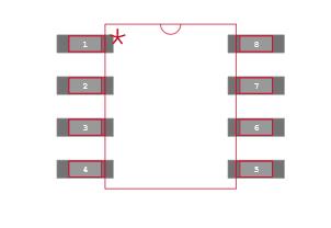
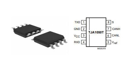
TJA1050 Pinout

TJA1050 Pinout


SYMBOL pin Description
TXD 1 transmit data input; reads in   data from the CAN controller to the bus line drivers
   
GND 2 ground
Vcc 3 supply voltage
RXD 4 receive data output; reads   out
    data from the bus lines to the CAN controller
   
Vreft 5 reference voltage output
CANL 6 L OW-level CAN bus line
CANH 7 HIGH-level CAN bus line
S 8 select input for high-speed mode   or silent mode
   

TJA1050 CAD Model

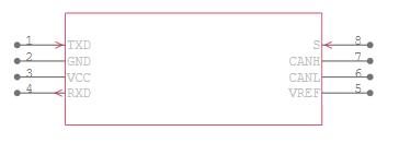
TJA1050 Symbol

TJA1050 Footprint

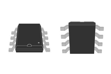
TJA1050 3D Model

TJA1050 Description

The TJA1050 is the interface between the Controller Area Network (CAN) protocol controller and the physical bus. The device provides differential transmit capability to the bus and differential receive capability to the CAN controller. The TJA1050 is the third Philips high-speed CAN transceiver after the PCA82C250 and the PCA82C251. 

The most important differences are: 

• Much lower electromagnetic emission due to optimal matching of the output signals CANH and CANL 

• Improved behaviour in case of an unpowered node 

• No standby mode. 

This makes the TJA1050 eminently suitable for use in nodes that are in a power-down situation in partially powered networks.

TJA1050 Features

  • Fully compatible with the"ISO 11898" standard

  • High speed (up to 1 Mbaud)

  • Very low ElectroMagnetic Emission (EME)

  • Differential receiver with wide common-mode range for high ElectroMagnetic Immunity (EMI)

  • An unpowered node does not disturb the bus lines

  • Transmit Data (TXD) dominant time-out function

  • The silent mode in which the transmitter is disabled

  • Bus pins protected against transients in an automotive environment

  • Input levels compatible with 3.3 V and 5 V devices

  • Thermally protected

  • Short-circuit proof to the battery and to ground

  • At least 110 nodes can be connected

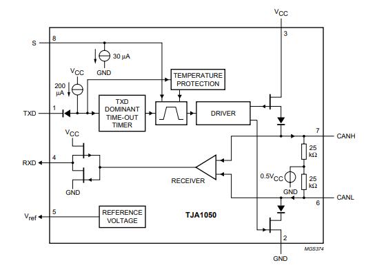
TJA1050 Block Diagram

The TJA1050 is the interface between the CAN protocol controller and the physical bus. It is primarily intended for high-speed automotive applications using baud rates from 60 kbaud up to 1 Mbaud. It provides differential transmit capability to the bus and differential receiver capability to the CAN protocol controller. It is fully compatible with the "ISO 11898" standard.

TJA1050 Block Diagram

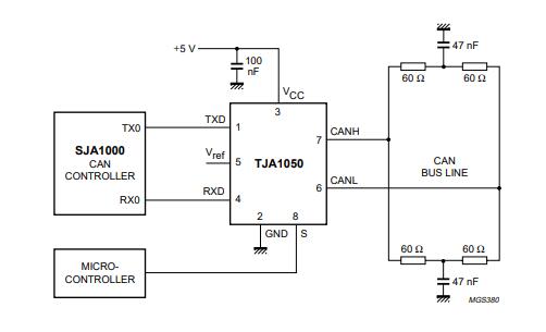
TJA1050 Circuit

TJA1050 Application Circuit

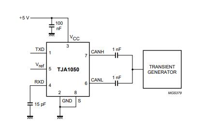
TJA1050 Test circuit for automotive transients

Specifications

TJA1050T/N,118 Tech Specifications

NXP USA Inc. TJA1050T/N,118 technical specifications, attributes, parameters and parts with similar specifications to NXP USA Inc. TJA1050T/N,118.

Product Attribute Attribute Value
Mounting TypeSurface Mount
Package / Case8-SOIC (0.154, 3.90mm Width)
Surface MountYES
Operating Temperature-40°C~150°C
PackagingTape & Reel (TR)
Published2002
JESD-609 Codee0
Part StatusObsolete
Moisture Sensitivity Level (MSL)1 (Unlimited)
Number of Terminations8Terminations
TypeTransceiver
HTS Code8542.39.00.01
Product Attribute Attribute Value
Voltage - Supply4.75V~5.25V
Terminal PositionDUAL
Terminal FormGULL WING
Peak Reflow Temperature (Cel)NOT SPECIFIED
Number of Functions1Function
Supply Voltage5V
Terminal Pitch1.27mm
Time@Peak Reflow Temperature-Max (s)NOT SPECIFIED
Base Part NumberTJA1050
Pin Count8
JESD-30 CodeR-PDSO-G8
Qualification StatusNot Qualified
Product Attribute Attribute Value
Power Supplies5V
Supply Current-Max0.075mA
Data Rate1000 Mbps
ProtocolCANbus
Number of Drivers/Receivers1/1Drivers/Receiver
DuplexHalf
Receiver Hysteresis70mV
Number of Transceivers1Transceiver
Length4.9mm
Height Seated (Max)1.75mm
Width3.9mm
RoHS StatusROHS3 Compliant
0 Products View Similar

Datasheet PDF

TJA1050T/N,118 Documents

Download datasheets and manufacturer documentation for TJA1050T/N,118

Datasheets
TJA1050

Frequently Asked Questions

What difference is between TJA1050 and MCP2551?
The TJA1050 is the interface between the Controller Area Network (CAN) protocol controller and the physical bus. The device provides differential transmit capability to the bus and differential receive capability to the CAN controller. The MCP2551 is a high-speed CAN, fault-tolerant device that serves as the interface between a CAN protocol controller and the physical bus. ... It also provides a buffer between the CAN controller and the high-voltage spikes that can be generated on the CAN bus by outside sources (EMI, ESD, electrical transients, etc.).
CAN voltage levels?
CAN voltage levels? The value should normally be between 2.5 and 3.5 Volts. Measured on a machine that is running, it will usually range between 2.7 and 3.3 Volts. The value should normally be between 1.5 and 2.5 Volts. Measured on a machine that is running, it will usually range between 1.7 and 2.3 Volts.
What condition to operate the TJA1050?
Operating Voltage: 4.75V to 5.25V Module Size: 22.0 (L) * 11.5 (W) * 3.3 (H) ( mm ) Module Weight: 0.8 – 1.0 grams Max No. of Nodes: up to 110 number of nodes
CAN Bus communication with Raspberry Pi?
Raspberry Pi doesn't have a built-in CAN-Bus (that's why we are doing all that...) But its GPIO includes an SPI Bus, which is supported by a large number of CAN controllers. SPI Bus uses 4 connections as follow: MOSI (Master Out Slave In).
How MCP2515 CAN BUS CONTROLLER Interface with TJA1050 DRIVER and SPI INTERFACE?
Support CAN V2.0B technical standard, communication rate 1Mb / S. Module 5V DC power supply, SPI interface protocol control 0 to 8 bytes long data field. 8MHZ crystal oscillator 120Ω terminal resistance Use High-speed CAN transceiver TJA1050 Impedance matching, guaranteed drive capability, long-distance data transmission, prevent signal radiation The working current: typical 5mA, standby current 1 microamp. Except for the power indicator. This is MCP2515 CAN Module TJA1050 Receiver SPI 51 Single Chip Program Routine Arduino with this module, you will find it easy to control any CAN Bus device by SPI interface with your MCU, such as Arduino UNO and Compatible with Arduino based microcontroller projects.
FAQ
What difference is between TJA1050 and MCP2551?
The TJA1050 is the interface between the Controller Area Network (CAN) protocol controller and the physical bus. The device provides differential transmit capability to the bus and differential receive capability to the CAN controller. The MCP2551 is a high-speed CAN, fault-tolerant device that serves as the interface between a CAN protocol controller and the physical bus. ... It also provides a buffer between the CAN controller and the high-voltage spikes that can be generated on the CAN bus by outside sources (EMI, ESD, electrical transients, etc.).
CAN voltage levels?
CAN voltage levels? The value should normally be between 2.5 and 3.5 Volts. Measured on a machine that is running, it will usually range between 2.7 and 3.3 Volts. The value should normally be between 1.5 and 2.5 Volts. Measured on a machine that is running, it will usually range between 1.7 and 2.3 Volts.
What condition to operate the TJA1050?
Operating Voltage: 4.75V to 5.25V Module Size: 22.0 (L) * 11.5 (W) * 3.3 (H) ( mm ) Module Weight: 0.8 – 1.0 grams Max No. of Nodes: up to 110 number of nodes
CAN Bus communication with Raspberry Pi?
Raspberry Pi doesn't have a built-in CAN-Bus (that's why we are doing all that...) But its GPIO includes an SPI Bus, which is supported by a large number of CAN controllers. SPI Bus uses 4 connections as follow: MOSI (Master Out Slave In).
How MCP2515 CAN BUS CONTROLLER Interface with TJA1050 DRIVER and SPI INTERFACE?
Support CAN V2.0B technical standard, communication rate 1Mb / S. Module 5V DC power supply, SPI interface protocol control 0 to 8 bytes long data field. 8MHZ crystal oscillator 120Ω terminal resistance Use High-speed CAN transceiver TJA1050 Impedance matching, guaranteed drive capability, long-distance data transmission, prevent signal radiation The working current: typical 5mA, standby current 1 microamp. Except for the power indicator. This is MCP2515 CAN Module TJA1050 Receiver SPI 51 Single Chip Program Routine Arduino with this module, you will find it easy to control any CAN Bus device by SPI interface with your MCU, such as Arduino UNO and Compatible with Arduino based microcontroller projects.

TAGS

Share