ATTENTION: Due to increased demand and order volume, processing time may take an additional 1-3 business days.
HomeCommunitySubjectTL494 Control Circuit: Features, Specifications and Applications

TL494 Control Circuit: Features, Specifications and Applications

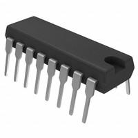
TEXAS INSTRUMENTS - TL494IN - IC, CONTROLLER, PWM The TL494 device incorporates all the functions required in the construction of a pulse-widthmodulation (PWM) control circuit on a single chip.

313

Mar 3, 2021

Xanthe

TEXAS INSTRUMENTS - TL494IN - IC, CONTROLLER, PWM

The TL494 device incorporates all the functions required in the construction of a pulse-widthmodulation (PWM) control circuit on a single chip. Designed pr amarily for power-supply control, this device offers the flexibility to tailor the power-supply control circuitry to a specific application.
TL494IN

3420In Stock
Min.: 1 Mult.: 1
Quantity Unit Price Ext. Price
1+ $0.64863$0.65
10+ $0.61192$6.12
100+ $0.57728$57.73
500+ $0.5446$272.3
1000+ $0.51378$513.78
Unit Price:$0.64863
Subtotal: $0.65
Looking for a better price? Want a lower wholesale price? Please send an RFQ, and we will respond immediately.
Quick Links

TL494 Decription

The TL494 device incorporates all the functions required in the construction of a pulse-widthmodulation (PWM) control circuit on a single chip. Designed pr amarily for power-supply control, this device offers the flexibility to tailor the power-supply control circuitry to a specific application.
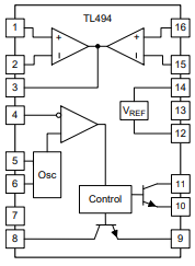
The TL494 device contains two error amplifiers, an on-chip adjustable oscillator, a dead-time control (DTC) comparator, a pulse-steering control flip-flop, a 5-V, 5%-precision regulator, and output-control circuits. The error amplifiers exhibit a common-mode voltage range from –0.3 V to VCC – 2 V. The dead-time control comparator has a fixed offset that provides approximately 5% dead time. The on-chip oscillator can be bypassed by terminating RT to the reference output and providing a sawtooth input to CT, or it can drive the common circuits in synchronous multiple-rail power supplies. The uncommitted output transistors provide either common-emitter or emitter-follower output capability. The TL494 device provides for push-pull or singleended output operation, which can be selected through the output-control function. The architecture of this device prohibits the possibility of either output being pulsed twice during push-pull operation. The TL494C device is characterized for operation from 0°C to 70°C. The TL494I device is characterized for operation from –40°C to 85°C.

TL494 Features

• Complete PWM Power-Control Circuitry 

• Uncommitted Outputs for 200-mA Sink or Source Current 

• Output Control Selects Single-Ended or Push-Pull Operation 

• Internal Circuitry Prohibits Double Pulse at Either Output 

• Variable Dead Time Provides Control Over Total Range 

• Internal Regulator Provides a Stable 5-V Reference Supply With 5% Tolerance 

• Circuit Architecture Allows Easy Synchronization


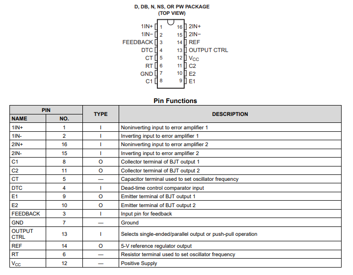
TL494 Pins

Specifications

Texas Instruments TL494IN technical specifications, attributes, parameters and parts with similar specifications to Texas Instruments TL494IN.

TL494IN Tech Specifications

Texas Instruments TL494IN technical specifications, attributes, parameters and parts with similar specifications to Texas Instruments TL494IN.

Product Attribute Attribute Value
Lifecycle StatusACTIVE (Last Updated: 4 days ago)
Factory Lead Time6 Weeks
Mounting TypeThrough Hole
Package / Case16-DIP (0.300, 7.62mm)
Surface MountNO
Number of Pins16Pins
Weight951.693491mg
Operating Temperature-40°C~85°C TA
PackagingTube
JESD-609 Codee4
Part StatusActive
Moisture Sensitivity Level (MSL)1 (Unlimited)
Number of Terminations16Terminations
ECCN CodeEAR99
Terminal FinishNickel/Palladium/Gold (Ni/Pd/Au)
Terminal PositionDUAL
Product Attribute Attribute Value
Supply Voltage15V
Frequency300kHz
Base Part NumberTL494
FunctionStep-Up, Step-Down, Step-Up/Step-Down
Number of Outputs2Outputs
Output Voltage40V
Output TypeTransistor Driver
Operating Supply Voltage15V
Input Voltage-Nom15V
Analog IC - Other TypeSWITCHING CONTROLLER
Output ConfigurationPositive
Output Current200mA
Voltage - Supply (Vcc/Vdd)7V~40V
Control FeaturesDead Time Control, Frequency Control
Input Voltage (Min)7V
TopologyBuck, Boost, Flyback, Forward Converter, Full-Bridge, Half-Bridge, Push-Pull
Product Attribute Attribute Value
Control ModeVOLTAGE-MODE
Frequency - Switching1kHz~300kHz
Control TechniquePULSE WIDTH MODULATION
Rise Time100ns
Synchronous RectifierNo
Fall Time (Typ)40 ns
Max Duty Cycle45 %
Output Phases1
Height5.08mm
Length19.3mm
Width6.35mm
Thickness3.9mm
REACH SVHCNo SVHC
RoHS StatusROHS3 Compliant
Lead FreeLead Free
0 Products View Similar

TL494 Block Diagram

TL494 Applications

• Desktop PCs 

• Microwave Ovens 

• Power Supplies: AC/DC, Isolated, With PFC, > 90 W 

• Server PSUs 

• Solar Micro-Inverters 

• Washing Machines: Low-End and High-End 

• E-Bikes 

• Power Supplies: AC/DC, Isolated, No PFC, < 90 W 

• Power: Telecom/Server AC/DC Supplies: Dual Controller: Analog 

• Smoke Detectors 

• Solar Power Inverters


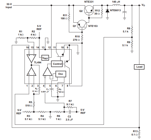
Typical Application

Design Requirements 

• VI = 32 V 

• VO = 5 V 

• IO = 10 A 

• fOSC = 20-kHz switching frequency 

• VR = 20-mV peak-to-peak (VRIPPLE) 

• ΔIL = 1.5-A inductor current change

Datasheet PDF

Download datasheets and manufacturer documentation for Texas Instruments TL494IN.

TL494IN Documents

Download datasheets and manufacturer documentation for TL494IN

Frequently Asked Questions

What is the difference between a power circuit and a control circuit?
A control circuit is the part of the circuit where panel switches. limit switches and sensors are connected to control a larger machine. They provide the switching and control of the power circuit. Power circuits are the connections to motors, overload elements and contactors carrying high current.
How do you make a control circuit?
A motor control circuit contains two basic components: a disconnecting switch and a starter. The disconnecting switch is always placed between the supply line and the starter. The switch and starter are sometimes mounted in the same enclosure to make a combination starter.
How does a control circuit work?
A control circuit is a special type of circuit used to control the operation of a completely separate power circuit. Consider a 1,000 horsepower, large industrial motor driving a water pump. The motor is connected to a high voltage electrical supply of 2,400 volts.
FAQ
What is the difference between a power circuit and a control circuit?
A control circuit is the part of the circuit where panel switches. limit switches and sensors are connected to control a larger machine. They provide the switching and control of the power circuit. Power circuits are the connections to motors, overload elements and contactors carrying high current.
How do you make a control circuit?
A motor control circuit contains two basic components: a disconnecting switch and a starter. The disconnecting switch is always placed between the supply line and the starter. The switch and starter are sometimes mounted in the same enclosure to make a combination starter.
How does a control circuit work?
A control circuit is a special type of circuit used to control the operation of a completely separate power circuit. Consider a 1,000 horsepower, large industrial motor driving a water pump. The motor is connected to a high voltage electrical supply of 2,400 volts.

TAGS

Share