Bycicle LED Flasher Light with TLC555
TEXAS INSTRUMENTS TLC555CD IC, TIMER CMOS, SMD, SOIC8, 555
TLC555 is a Timer. This article mainly introduce its pinout, package, datasheet and other detailed information about Texas Instruments TLC555.

TEXAS INSTRUMENTS TLC555CD IC, TIMER CMOS, SMD, SOIC8, 555
431
Jul 22, 2021
Janice Daniell
Bycicle LED Flasher Light with TLC555
TEXAS INSTRUMENTS TLC555CD IC, TIMER CMOS, SMD, SOIC8, 555
TLC555 is a Timer. This article mainly introduce its pinout, package, datasheet and other detailed information about Texas Instruments TLC555.
TLC555CD
| Quantity | Unit Price | Ext. Price |
|---|---|---|
| 1+ | $0.56324 | $0.56 |
| 10+ | $0.53136 | $5.31 |
| 100+ | $0.50129 | $50.13 |
| 500+ | $0.47291 | $236.46 |
| 1000+ | $0.44614 | $446.14 |
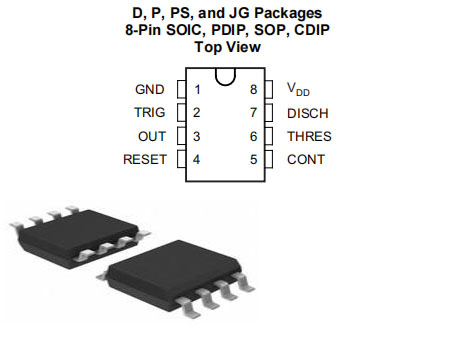
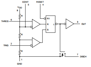
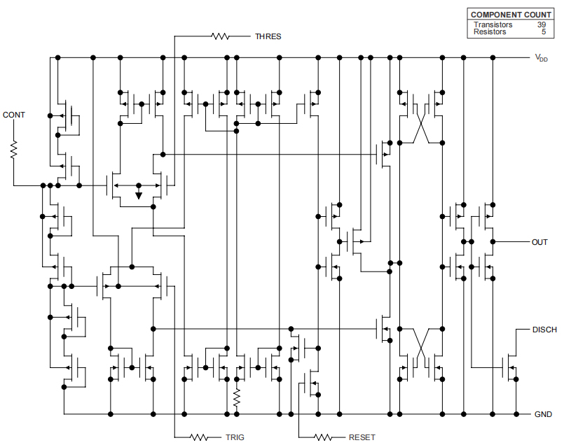
TLC555 is a monolithic timing circuit manufactured Use TI LinCMOS™ process. Timer is full Compatible with CMOS, TTL and MOS logic and The operating frequency is up to 2 MHz. Because of its high input impedance, the device supports smaller timing capacitors supported by NE555 Or LM555. Therefore, more accurate time delay and Oscillation is possible. Low power consumption In the entire power supply voltage range. Like NE555, the trigger level of TLC555 is equal to to about one-third of the supply voltage and The threshold level is approximately equal to two thirds voltage. These levels can pass Use the control voltage terminal (CONT). when the trigger input (TRIG) is lower than the trigger level, the trigger is set and the output goes high. If TRIG is Input above the trigger level and threshold (THRES) above the threshold level, the trigger is reset, the output is low. Reset input (RESET) can override all other inputs and can be used for start a new timing period. If reset is low, the flip-flop is reset and the output is low. Whenever low output, providing low impedance path between the discharge terminal (DISCH) and GND. All unused inputs must be bound to appropriate logic level to prevent false triggering.
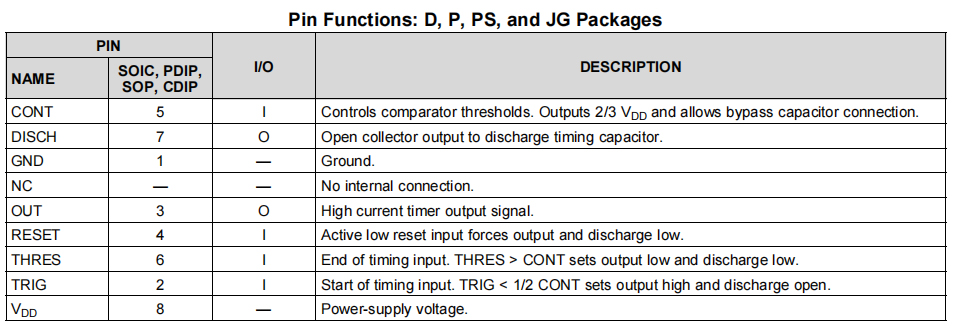
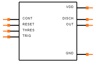
Symbol
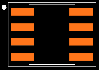
Footprint
3D Model
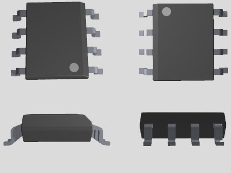
• Very low power consumption:
– 1-mW typical at VDD = 5 V
• Capable of operating in astable mode
• CMOS output capable of rail-to-rail swing
• High output current capability
– Sink current: 100-mA typical
– Source: 10-mA typical
• The output is fully compatible with CMOS, TTL and
MOS
• Low power supply current reduces spikes during output
transition
• 2 V to 15 V single power supply operation
• Function interchangeable with NE555; has same pinout
• ESD protection exceeds 2000 V/MIL-STD-883C, Method 3015.2
• Can be used in Q-temp cars
– High reliability automotive applications
- Configuration control and printing support
- Compliance with automotive standards
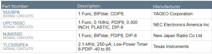
Texas Instruments TLC555CD technical specifications, attributes, parameters and parts with similar specifications to Texas Instruments TLC555CD.
Texas Instruments TLC555CD technical specifications, attributes, parameters and parts with similar specifications to Texas Instruments TLC555CD.
| Product Attribute | Attribute Value | |
|---|---|---|
| Lifecycle Status | ACTIVE (Last Updated: 5 days ago) | |
| Factory Lead Time | 6 Weeks | |
| Contact Plating | Gold | |
| Mount | Surface Mount | |
| Mounting Type | Surface Mount | |
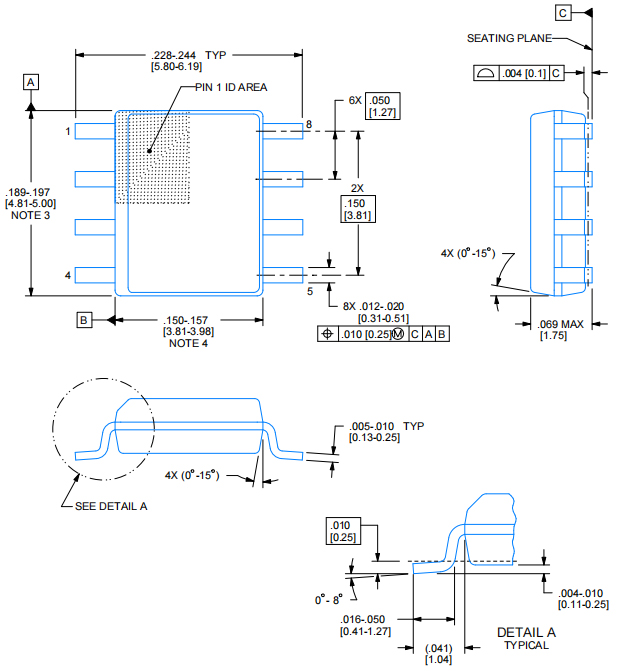
| Package / Case | 8-SOIC (0.154, 3.90mm Width) | |
| Number of Pins | 8Pins | |
| Weight | 72.603129mg | |
| Operating Temperature | 0°C~70°C | |
| Packaging | Tube | |
| Series | LinCMOS™ | |
| JESD-609 Code | e4 | |
| Pbfree Code | yes | |
| Part Status | Active | |
| Moisture Sensitivity Level (MSL) | 1 (Unlimited) | |
| Number of Terminations | 8Terminations | |
| Termination | SMD/SMT |
| Product Attribute | Attribute Value | |
|---|---|---|
| ECCN Code | EAR99 | |
| Type | 555 Type, Timer/Oscillator (Single) | |
| Max Power Dissipation | 725mW | |
| Voltage - Supply | 5V | |
| Terminal Position | DUAL | |
| Terminal Form | GULL WING | |
| Peak Reflow Temperature (Cel) | 260 | |
| Number of Functions | 1Function | |
| Current Rating | 250A | |
| Frequency | 2.1MHz | |
| Base Part Number | TLC555 | |
| Pin Count | 8 | |
| Power Supplies | 5V | |
| Number of Channels | 1Channel | |
| Nominal Supply Current | 250μA | |
| Power Dissipation | 725mW | |
| Output Current | 15mA |
| Product Attribute | Attribute Value | |
|---|---|---|
| Quiescent Current | 250μA | |
| Current - Supply | 360μA | |
| Supply Current-Max (Isup) | 0.4mA | |
| High Level Output Current | -10mA | |
| Low Level Output Current | 100mA | |
| Voltage - Supply (Min) | 2V | |
| Ambient Temperature Range High | 70°C | |
| Height | 1.75mm | |
| Length | 4.9mm | |
| Width | 3.91mm | |
| Thickness | 1.58mm | |
| REACH SVHC | No SVHC | |
| Radiation Hardening | No | |
| RoHS Status | ROHS3 Compliant | |
| Lead Free | Lead Free |

• Precise timing
• Pulse generation
• Sequential timing
• Time delay generation
• Pulse width modulation
• Pulse position modulation
• Linear ramp generator
Texas Instruments Incorporated (TI) is an American technology company headquartered in Dallas, Texas, that designs and manufactures semiconductors and various integrated circuits, which it sells to electronics designers and manufacturers globally.[6] It is one of the top 10 semiconductor companies worldwide based on sales volume.The company's focus is on developing analog chips and embedded processors, which account for more than 80% of its revenue.TI also produces TI digital light processing technology and education technology products including calculators, microcontrollers and multi-core processors. The company holds 45,000 patents worldwide as of 2016.
Download datasheets and manufacturer documentation for Texas Instruments TLC555CD.
Download datasheets and manufacturer documentation for TLC555CD
TAGS
Comments