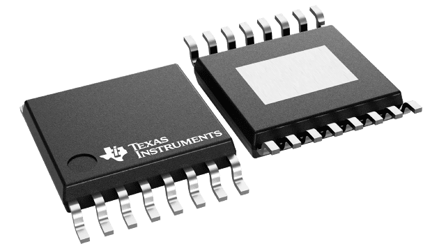
IC LED DRIVER LIN DIM 16HTSSOP
TPS92630QPWPRQ1 is an Automotive Three-channel Linear LED driver with Analog and PWM dimming. This passage will cover its manufacturer, specification, datasheet, and others.

IC LED DRIVER LIN DIM 16HTSSOP TPS92630QPWPRQ1 is an Automotive Three-channel Linear LED driver with Analog and PWM dimming. This passage will cover its manufacturer, specification, datasheet, and others.
847
Mar 4, 2022
Moore Garcia
IC LED DRIVER LIN DIM 16HTSSOP
TPS92630QPWPRQ1 is an Automotive Three-channel Linear LED driver with Analog and PWM dimming. This passage will cover its manufacturer, specification, datasheet, and others.
TPS92630QPWPRQ1
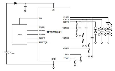
The TPS92630QPWPRQ1 is a three-channel constant-current regulator with individual PWM dimming for high-brightness red or white LEDs in vehicle lighting. When paralleled, each channel has a current capability of up to 150 mA, for a total current capability of 450 mA. The device ensures that channels and devices are well-matched in terms of current. LED common-cathode connections are possible with a high-side current source.
Even when differing numbers of LEDs are connected to the output, the complex control loop allows for great precision between channels. Each channel is dimmed or disabled when a separate PWM channel is used.
Automotive LED Lighting Applications, Such As:
• Daytime Running Light
• Position Light
• Fog Light
• Rear Light
• Stop or Taillight
• Interior Lighting
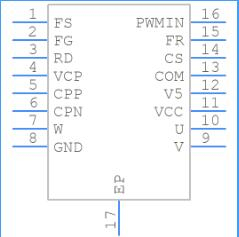
Symbol
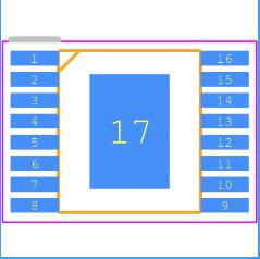
Footprint
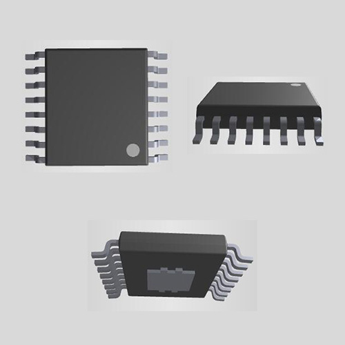
3D Models
Texas Instruments TPS92630QPWPRQ1 technical specifications, attributes, parameters and parts with similar specifications to Texas Instruments TPS92630QPWPRQ1.
| Product Attribute | Attribute Value | |
|---|---|---|
| Lifecycle Status | ACTIVE (Last Updated: 3 days ago) | |
| Factory Lead Time | 6 Weeks | |
| Contact Plating | Gold | |
| Mount | Surface Mount | |
| Mounting Type | Surface Mount | |
| Package / Case | 16-PowerTSSOP (0.173, 4.40mm Width) | |
| Number of Pins | 16Pins | |
| Operating Temperature | -40°C~125°C TA | |
| Packaging | Tape & Reel (TR) | |
| Series | Automotive, AEC-Q100 | |
| JESD-609 Code | e4 | |
| Pbfree Code | yes | |
| Part Status | Active | |
| Moisture Sensitivity Level (MSL) | 3 (168 Hours) | |
| Number of Terminations | 16Terminations | |
| ECCN Code | EAR99 |
| Product Attribute | Attribute Value | |
|---|---|---|
| Type | Linear | |
| Applications | Automotive | |
| Terminal Position | DUAL | |
| Terminal Form | GULL WING | |
| Peak Reflow Temperature (Cel) | 260 | |
| Number of Functions | 1Function | |
| Supply Voltage | 14V | |
| Time@Peak Reflow Temperature-Max (s) | NOT SPECIFIED | |
| Base Part Number | TPS92630 | |
| Current - Supply (Max) | 850μA | |
| Number of Outputs | 3Outputs | |
| Max Output Current | 150mA | |
| Current - Output | 150mA | |
| Quiescent Current | 600μA | |
| Max Output Voltage | 40V | |
| Voltage - Output | 4V~75V |
| Product Attribute | Attribute Value | |
|---|---|---|
| Min Input Voltage | 5V | |
| Max Input Voltage | 40V | |
| Output Current per Channel | 450mA | |
| Internal Switch(s) | Yes | |
| Dimming | Analog, PWM | |
| Min Input Voltage (DC) | 5V | |
| Number of Segments | 7Segments | |
| Voltage - Supply (Max) | 40V | |
| Multiplexed Display Capability | NO | |
| Height | 1.2mm | |
| Length | 5mm | |
| Width | 4.4mm | |
| Thickness | 1mm | |
| RoHS Status | ROHS3 Compliant | |
| Lead Free | Lead Free |
Qualified for Automotive Applications
AEC-Q100 Qualified With the Following Results:
– Device Temperature Grade 1: –40°C to 125 °C Ambient Operating Temperature Range
– Device HBM ESD Classification Level H2
– Device CDM ESD Classification Level C3B
3-Ch. LED Driver With Analog and PWM Dimming
Wide Input-Voltage Range: 5 V–40 V
Adjustable Constant Output Current Set by reference Resistor
– Max. Current: 150 mA per Channel
– Max. Current: 450 mA in Parallel Operation Mode
– Accuracy: ±1.5% per Channel When I(IOUTx) > 30 mA
– Accuracy: ±2.5% per Device When I(IOUTx) > 30 mA
Parallel Outputs for Higher Current Using MultipleICs or Multiple Channels of a Single IC
Low Dropout Voltage
– Max. Dropout: 40 0 mV at 60 mA per Channel
– Max. Dropout: 0.9 V at 150 mA per Channel
Independent PWM Dimming per Channel
Open and Shorted LED Detection With DeglitchTimer
LED-String Voltage Feedback per Channel for single-LED Short Detection
Separate Fault Pin for Single-LED Short Failure
Fault Pin for Open, Short, and Thermal ShutdownFailure Reporting, Allowing Parallel Bus Connection up to 15 Devices
Device Accommodates a Slow Input-Voltage dV/dt(0.5 V/min) With No Issues
Operating Junction Temperature Range –40°C to150°C
Package: 16-Pin Thermally Enhanced PWP Package (HTSSOP)
| Height | 1.2mm |
| Length | 5mm |
| Thickness | 1mm |
| Width | 4.4mm |

Constant LED -Current Setting
Control of the three LED output channels is through separate linear current regulators. A common external resistor sets the current in each channel.
PWM Control
The device features a separate PWM dimming control pin for each output channel. PWM inputs also function as shutdown pins when output is unused.
FAULT Diagnostics
The TPS92630QPWPRQ1 device has two fault pins, FAULT and FAULT _S. FAULT _S is a dedicated fault pin for the single LED short failure and FAULT is for general faults, that is, short, open, and thermal shutdown.
Short-Circuit Detection
The device includes three internal comparators for LED forward-voltage measurement. With external resistor dividers, the device compares total LED forward voltage with the internal reference voltage. This feature enables the detection of one or more shorted LED s.
Open-Load Detection
Detection of an open-load condition occurs when the voltage across the channel, V(VIN) – V(IOUTx), is less than the open-load detection voltage, V(OLV)
Thermal Foldback
The TPS92630-Q1 device integrates thermal shutdown protection to prevent the device from overheating.
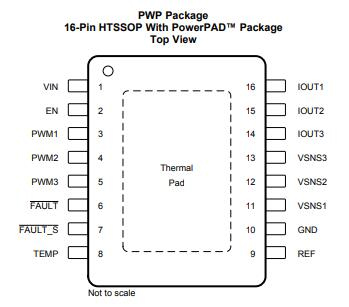
| PIN | |||
| Name | NO. | I/O | DESCRIPTION |
| EN | 2 | I | Enable and shut down |
| FAULT | 6 | I/O | Fault pin. Leave floating if not used |
| FAULT_S | 7 | I/O | Single-LED short fault. Leave floating if not used |
| GND | 10 | - | Ground |
| IOUT1 | 16 | O | Current output pin. Connect to VSNS1 if not used. |
| IOUT2 | 15 | O | Current output pin. Connect to VSNS2 if not used. |
| IOUT3 | 14 | O | Current output pin. Connect to VSNS3 if not used. |
| PWM1 | 3 | I | PWM input and channel ON or OFF. Tie to GND if this channel is not used |
| PWM2 | 4 | I | PWM input and channel ON or OFF. Tie to GND if this channel is not used |
| PWM3 | 5 | I | PWM input and channel ON or OFF. Tie to GND if this channel is not used |
| REF | 9 | O | Reference resistor pin for the normal current setting |
| TEMP | 8 | I/O | Temperature foldback threshold program. Tie to GND if not used. |
| VIN | 1 | Input pin – VBAT supply | |
| VSNS1 | 11 | String voltage sense. Connect to IOUT1 if not used | |
| VSNS2 | 12 | String voltage sense. Connect to IOUT2 if not used | |
| VSNS3 | 13 | String voltage sense. Connect to IOUT3 if not used | |
| Thermal pad | - | - | Connect to GND |
Download datasheets and manufacturer documentation for TPS92630QPWPRQ1
TAGS
Comments