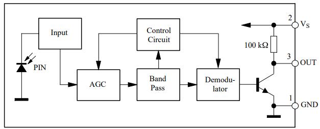
TSOP1738 Block Diagram
AGE
Internal components can be seen clearly in the block diagram, but the use of each component is a reason. Although an IR receiver can work on its own, other components in the TSOP make it smart and secure. The IR is connected to the AGC first (Automatic Gain Control). Different sorts of input signals from the IR receiver are amplified using AGC. The output of the AGC is then sent to the Bandpass filter.
Band Pass Filter
In TSOP, the bandpass filter serves various purposes. It converts incoming analog signals to digital output levels before sending them to the demodulator. Because it is common and can be found anywhere, the combination of AGC and bandpass allows it to avoid any ambient light, particularly sunshine. Even though the device has built-in sun protection, the company recommended that it be used at a closer range. Weather changes can sometimes impact the amount of sunshine available, which can affect TSOP transmission. The bandpass filter additionally restricts the IC's operation to a certain frequency of 38 kHz.
Demodulator
On one end, the demodulator is connected to the NPN transistor, and on the other, to the Band Pass Filter. The bandpass filter's output data will be fed into the demodulator, which will use low input signals to operate the NPN transistor. On the collector side, the NPN transistor is directly connected to the power and output, and on the emitter side, it is directly connected to the ground. Every low signal disables the NPN transistor, allowing power to flow to the output pin.