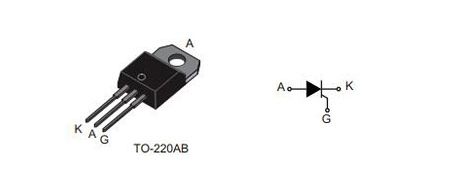
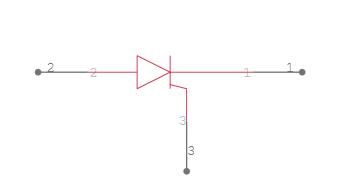
The switches S1 and S2 are initially in a normally-open state. Thyristors remain reversed biased until the gate pulse is given when the supply is turned on. We used Push Button S2 to provide the gate pulse. Even if we release the push button S2, the thyristor goes on and latches as the S2 switch closes.
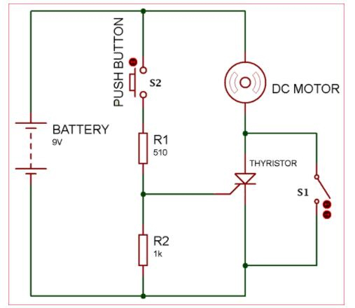
TYN612 Typical Application Circuit
The only method to stop the Thyristor from conducting in this typical application circuit once it has self-latched into the ON state is to disrupt the supply across the Thyristor. We accomplish this by using switch S1, which short-circuits the anode and cathode, lowering the holding current to its threshold value. As a result, the Thyristor is reset or turned off.
Resistance R1 is used to provide sufficient gate current to turn ON the thyristor. Resistance R2 is used for decreasing the gate sensitivity and increasing the DV/DT capability. Therefore, it prevents Thyristor from false triggering.
R1 was employed to supply enough gate current to turn the thyristor on. The R2 resistance is utilized to reduce gate sensitivity and boost DV/DT capacity. As a result, it prevents Thyristor from triggering incorrectly.