ATTENTION: Due to increased demand and order volume, processing time may take an additional 1-3 business days.
HomeCommunitySubjectUC3843 PWM Controller: Pinout, Datasheet and Uses

UC3843 PWM Controller: Pinout, Datasheet and Uses

IC REG CTRLR 14SOIC Hello everyone! I hope you all are fine today.

1443

Aug 13, 2021

Lena Bentham

UC3843 Switching Power Supply 12V, 10A


IC REG CTRLR 14SOIC

Hello everyone! I hope you all are fine today. Today, we will have a discussion about UC3843. UC3843 is a current mode PWM controller. This article mainly introduce pinout, datasheet, uses and other detailed information about On Semiconductor UC3843.

UC3843D

1459In Stock
Min.: 1 Mult.: 1
Quantity Unit Price Ext. Price
1+ $1.35186$1.35
10+ $1.27534$12.75
100+ $1.20315$120.32
500+ $1.13505$567.53
1000+ $1.0708$1070.8
Unit Price:$1.35186
Subtotal: $1.35
Looking for a better price? Want a lower wholesale price? Please send an RFQ, and we will respond immediately.
Quick Links

UC3843 Description

UC3843 is basically a current mode Pulse Width Modulation (PWM) controller having fixed frequency. It is basically designed for DC to DC converter purposes as well as off line applications with minimum external components. UC3843 has three different packages.


UC3843 has several different features which make it ideal and useful for a lot of real life applications. These features may include trimmed oscillator for the control of accurate duty cycle, high gain amplifier, a temperature compensated reference, current sensing comparator and to control power MOSFET, there is a high current totem-pole output. 


Moreover, some other features include temperature compensated reference and current sensing. UC 3843 can be used at several different places e.g.in switching regulators having any of the polarities as well as in transformer coupled DC to DC converters. The UC3843 have UVLO thresholds of 8.5V(on) The  UC3843 can operate within 100% duty cycle. 

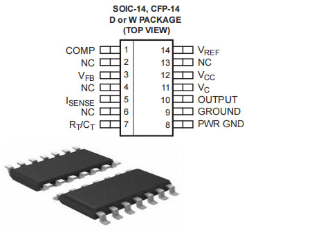
UC3843 Pinout

UC3843 CAD Model

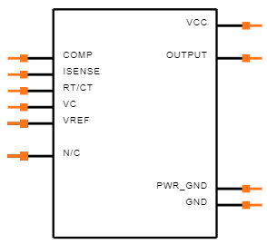
Symbol


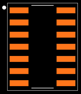
Footprint


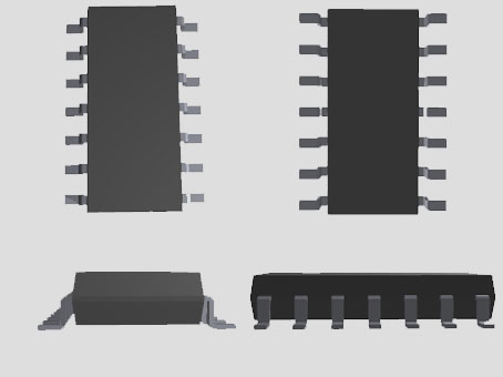
3D Model

UC3843 Features

● Current-Mode PWM controller

● Operating Voltage: 7.0V to 8.2V

● Output pin current: 1A

● Analog input range: -0.3 to 6.3V

● Oscillation Frequency: 52 Typically Gain: 3V

● Maximum source current: 22mA

● Low Output Voltage: 0.08V

● High Output Voltage: 13.5V

● Low startup current(<1 mA)

● Pulse by pulse current limiting

● Low output resistance

● Double pulse surpression

● High current totem pole outputs

● Maximum Duty Clamp

● UVLO With Hysteresis

● Operating Frequency up to 500KHz

● Optimized For Off-line and DC-to-DC Converters

● Automatic Feed Forward Compensation Internally implemented circuits include under-voltage

● Internally Trimmed Bandgap Reference

● Low RO Error Amp

Specifications

ON Semiconductor UC3843D technical specifications, attributes, parameters and parts with similar specifications to ON Semiconductor UC3843D.

UC3843D Tech Specifications

ON Semiconductor UC3843D technical specifications, attributes, parameters and parts with similar specifications to ON Semiconductor UC3843D.

Product Attribute Attribute Value
MountSurface Mount
Mounting TypeSurface Mount
Package / Case14-SOIC (0.209, 5.30mm Width)
Number of Pins14Pins
Operating Temperature0°C~70°C TA
PackagingTube
Published2002
Part StatusObsolete
Moisture Sensitivity Level (MSL)1 (Unlimited)
Frequency500kHz
Base Part NumberUC3843
Product Attribute Attribute Value
FunctionStep-Up, Step-Up/Step-Down
Number of Outputs1Output
Output Voltage13.5V
Output TypeTransistor Driver
Voltage30V
Operating Supply Current17mA
Nominal Supply Current17mA
Output ConfigurationPositive
Output Current1A
Voltage - Supply (Vcc/Vdd)7.6V~30V
Control FeaturesFrequency Control
Product Attribute Attribute Value
TopologyBoost, Flyback
Frequency - SwitchingUp to 500kHz
Rise Time45ns
Synchronous RectifierNo
Fall Time (Typ)35 ns
Nominal Input Voltage25V
Max Duty Cycle100 %
Duty Cycle (Max)97%
REACH SVHCNo SVHC
RoHS StatusRoHS Compliant
Lead FreeLead Free
0 Products View Similar

UC3843 Alternatives

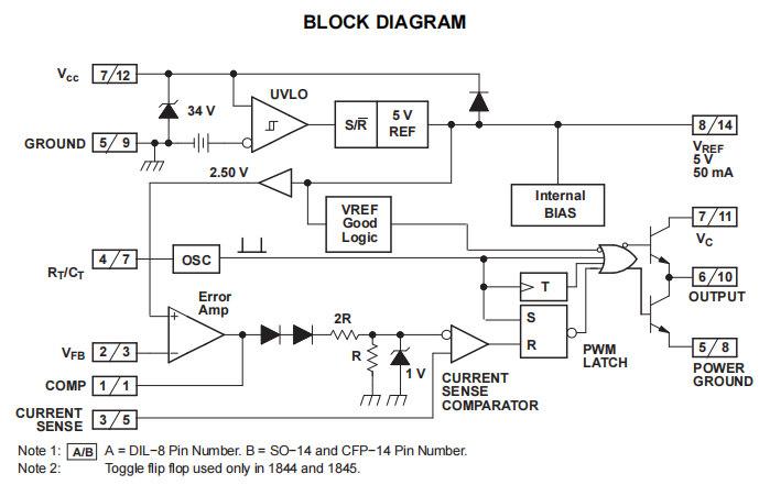
UC3843 Block Diagram

Where to use UC3843?

The UC3843 IC is a current Mode PWM Controller, meaning it can be used to provide a constant current by varying the output voltage to the load. While building Switch mode supplies with feedback there are two modes of control that is commonly used, one is voltage mode control where the output voltage will kept constant irrespective of the current (CV mode) and the other is current mode control where the output current will be constant (C mode) irrespective of the voltage.

The UC3843 can be used to regulate or limit current in application like SMPS, RPS, DC-DC Converters, Line voltage regulators etc.. So if you are looking for an IC to  produce PWM signals for controlling a power switch based on the current flowing through the circuit then this IC might be the right choice for you.

How to use UC3843?

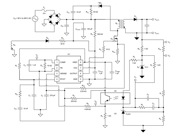
Although the IC performs a sophisticated job, using it in a circuit is fairly simple and can be done with minimum number if external components which make this IC to be a preferable choice among designers. A sample application circuit of this IC is shown below.

The IC has an under voltage protection, so care should be taken to make sure that it has an operating voltage between 7V to 8.2V. The output pin of the IC is connected to the gate driver circuit of the Power switch which is to be switched. The output pin can source upto 1A ad hence a current limiting resistor will be required. The VFB (Voltage feedback) pin acts as a feedback based on which the PWM signal is controlled. A shunt resistor is used to monitor the change in current in the circuit and then this difference voltage across the shunt is provided to the feedback pin.


The IC also has an internal oscillator which can be configured using by connecting the right value of capacitor and resistor to the pin Rt/Ct. The Datasheet recommends a value of between 470pf to 4.7nf and for the resistor a value between 5k to 100k. Refer the datasheet at the end of the page to know more about this IC. Also check out the Layout diagram at the bottom of the datasheet for a quick start. A more detailed application circuit is shown below.

Uc3843 Applications

■ SMPS (Switch mode Power Supplies) circuits

■ Transformers coupled DC-DC converter circuits

■ Electronics power supply

■ Battery drain circuit

■ Load machines

■ Switching regulators having any polarity

UC3843 Package

UC3843 Manufacturer

ON Semiconductor is a semiconductor supplier company, Products include power and signal management, logic, discrete, and custom devices for automotive, communications, computing, consumer, industrial, LED lighting, medical, military/aerospace and power applications. ON Semiconductor runs a network of manufacturing facilities, sales offices and design centers in North America, Europe, and the Asia Pacific regions. Its Headquarter is in Phoenix, Arizona.


Datasheet PDF

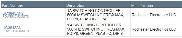
Download datasheets and manufacturer documentation for ON Semiconductor UC3843D.

UC3843D Documents

Download datasheets and manufacturer documentation for UC3843D

Frequently Asked Questions

1.What is the difference between TL2843B and UC3843?
The working temperature is different, the working temperature of TL2843 is 25-85℃, and the working temperature of UC3843 is 0-70℃. Can be interchanged.
2.What are the consequences of changing the reference voltage of UC3843?
The standard voltage is like a Zener diode in a voltage regulator circuit, the output voltage will rise.
3.How to repair the switching power supply of UC3843?
1). When repairing the switching power supply, first use a multimeter to check whether the power components are broken down and short-circuited, such as the power rectifier bridge stack, switching tube, high-frequency high-power rectifier tube; whether the high-power resistor that suppresses the surge current is blown. Then check whether the resistance of each output voltage port is abnormal. If the above components are damaged, they need to be replaced. (2). After the first step is completed, it can't work normally after turning on the power. Next, check the power factor module (PFC) and pulse width modulation module (PWM), check relevant information, and be familiar with the functions and functions of each pin of the PFC and PWM modules. A prerequisite for the normal operation of its modules.
4.How big is the sampling resistance of the switching power supply of UC3843?
The sampling resistance between the S pole of the field effect tube and the ground should be determined according to the maximum peak current of the primary side of the switching power supply, and the peak voltage of 1V cannot be exceeded at both ends of the resistance, or overcurrent protection will be used. The resistance in the electric car charger is 0.33 ohms.
5.How to use the pin 1 of UC3843?
It can be used for feedback and compensation. When used as feedback, connect pin 2 to ground and use it as negative feedback to receive the feedback voltage. When used for compensation, pin 2 is used as the feedback terminal, and a capacitor resistor is added between pin 1 and pin 2 to absorb the interference of the feedback terminal and ensure the purity of the signal.
FAQ
1.What is the difference between TL2843B and UC3843?
The working temperature is different, the working temperature of TL2843 is 25-85℃, and the working temperature of UC3843 is 0-70℃. Can be interchanged.
2.What are the consequences of changing the reference voltage of UC3843?
The standard voltage is like a Zener diode in a voltage regulator circuit, the output voltage will rise.
3.How to repair the switching power supply of UC3843?
1). When repairing the switching power supply, first use a multimeter to check whether the power components are broken down and short-circuited, such as the power rectifier bridge stack, switching tube, high-frequency high-power rectifier tube; whether the high-power resistor that suppresses the surge current is blown. Then check whether the resistance of each output voltage port is abnormal. If the above components are damaged, they need to be replaced. (2). After the first step is completed, it can't work normally after turning on the power. Next, check the power factor module (PFC) and pulse width modulation module (PWM), check relevant information, and be familiar with the functions and functions of each pin of the PFC and PWM modules. A prerequisite for the normal operation of its modules.
4.How big is the sampling resistance of the switching power supply of UC3843?
The sampling resistance between the S pole of the field effect tube and the ground should be determined according to the maximum peak current of the primary side of the switching power supply, and the peak voltage of 1V cannot be exceeded at both ends of the resistance, or overcurrent protection will be used. The resistance in the electric car charger is 0.33 ohms.
5.How to use the pin 1 of UC3843?
It can be used for feedback and compensation. When used as feedback, connect pin 2 to ground and use it as negative feedback to receive the feedback voltage. When used for compensation, pin 2 is used as the feedback terminal, and a capacitor resistor is added between pin 1 and pin 2 to absorb the interference of the feedback terminal and ensure the purity of the signal.

TAGS

Share