ATTENTION: Due to increased demand and order volume, processing time may take an additional 1-3 business days.
HomeCommunitySubjectWhat is TL494 PWM Controller?

What is TL494 PWM Controller?

PMIC - Voltage Regulators - DC DC Switching Controllers 16-DIP (0.300, 7.62mm) 0°C~70°C TA 200kHz Dead Time Control, Frequency Control SWITCHING CONTROLLER TL494 40kHz SWITCHMODE? ON SEMICONDUCTOR TL494CNGIC, PWM CONTROLLER, 40V, 16-DIP

946

Oct 31, 2021

Maria Christiana

TL494 Pulse Width Modulation Control Circuit

PMIC - Voltage Regulators - DC DC Switching Controllers 16-DIP (0.300, 7.62mm) 0°C~70°C TA 200kHz Dead Time Control, Frequency Control SWITCHING CONTROLLER TL494 40kHz SWITCHMODE™ ON SEMICONDUCTOR TL494CNGIC, PWM CONTROLLER, 40V, 16-DIP

The TL494 is a fixed frequency, pulse width modulation control circuit designed primarily for SWITCHMODE power supply control. This post will unlock more details about TL494. There is a huge range of Semiconductors, Capacitors, Resistors and ICs in stock. Welcome RFQ.
TL494CNG

Inquiry
Min.: 1 Mult.: 1
Price not displayed? Not available to buy online? Please send an RFQ, and we will respond immediately.
Quick Links

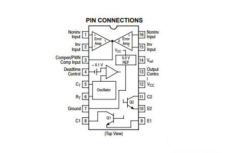
TL494 Pinout

TL494 Pinout


Pin Number

Pin Name

Description

1

1IN+

Noninverting input to error amplifier 1

2

1IN-

Inverting input to error amplifier 1

3

FEEDBACK

Input pin for feedback

4

DTC

Dead-time control comparator input

5

CT

Capacitor terminal used to set the   oscillator frequency

6

RT

Resistor terminal used to set the   oscillator frequency

7

GND

Ground Pin

8

C1

The collector terminal of BJT output 1

9

E1

The emitter terminal of BJT output 1

10

E2

The emitter terminal of BJT output 2

11

C2

The collector terminal of BJT output 2

12

VCC

Positive Supply

13

OUTPUT CTRL

Selects single-ended/parallel output or   push-pull operation

14

REF

The 5-V reference regulator output

15

2IN-

Inverting input to error amplifier 2

16

2IN+

Noninverting input to error amplifier 2

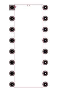
TL494 CAD Model

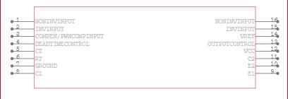
TL494 Symbol

TL494 Footprint

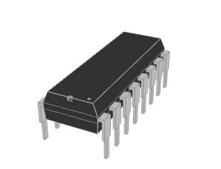
TL494 3D Model

What is TL494?

The TL494 IC is a fixed frequency current-mode PWM controller IC that includes all of the features needed to build a pulse-width modulation (PWM) control circuit on a single chip.

Where to Use TL494?

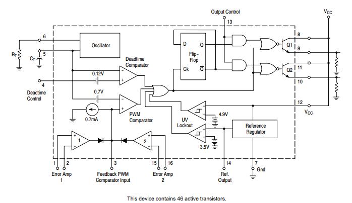
Regardless of buck or boost topology, the TL494 fixed frequency PWM Controller can be utilized for DC to DC conversion. By adjusting the output voltage to the load, the TL494 can deliver a constant current. An output control circuit, a flip flop, a dead time comparator, two error amplifiers, a 5V reference voltage, an oscillator, and a PWM comparator are all included in this IC.

So, if you're looking for an IC that can generate PWM signals to control a power switch based on the current flowing through the circuit, this IC would be a good fit.

How to Use TL494?

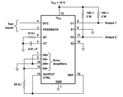
Inverting pins are linked to the ground and non-inverting pins are connected to the Ref pin. DTC and FEEDBACK pins receive test inputs. To control the oscillator frequency, pins 5 and 6 are linked to an external capacitor and resistor. When a sample of the 5-V output is compared to the reference, the error amplifier adjusts the PWM to maintain a consistent output current. The test circuit for TL494 is shown below.

TL494 Test Circuit

TL494 Feature

• Complete Pulse Width Modulation Control Circuitry 

• On−Chip Oscillator with Master or Slave Operation

• On−Chip Error Amplifiers 

• On−Chip 5.0 V Reference 

• Adjustable Deadtime Control 

• Uncommitted Output Transistors Rated to 500 mA Source or Sink 

• Output Control for Push−Pull or Single−Ended Operation 

• Undervoltage Lockout 

• NCV Prefix for Automotive and Other Applications Requiring Site and Control Changes 

• Pb−Free Packages are Available*

TL494 Application

  • Desktop PCs

  • Microwave Ovens

  • Server PSUs

  • Solar Micro-Inverters

  • Washing Machines: Low-End and High-End

  • E-Bikes

  • Power: Telecom/Server AC/DC Supplies:

  • Smoke Detectors

  • Solar Power Inverters

TL494 Circuit Diagram

TL494 Circuit Diagram

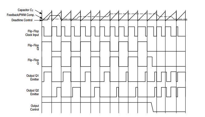
TL494 Timing Diagram

TL494 Equivalent

The equivalent for TL494:

  • UC3843

  • TL3842

Specifications

TL494CNG Tech Specifications

Rochester Electronics, LLC TL494CNG technical specifications, attributes, parameters and parts with similar specifications to Rochester Electronics, LLC TL494CNG.

Product Attribute Attribute Value
Mounting TypeThrough Hole
Package / Case16-DIP (0.300, 7.62mm)
Surface MountNO
Operating Temperature0°C~70°C TA
PackagingTube
SeriesSWITCHMODE™
Part StatusObsolete
Moisture Sensitivity Level (MSL)3 (168 Hours)
Number of Terminations16Terminations
ECCN CodeEAR99
Terminal PositionDUAL
Product Attribute Attribute Value
FunctionStep-Down, Step-Up/Step-Down
Number of Outputs2Outputs
Output TypeTransistor Driver
Input Voltage-Nom15V
Analog IC - Other TypeSWITCHING CONTROLLER
Output ConfigurationPositive
Voltage - Supply (Vcc/Vdd)7V~40V
Control FeaturesDead Time Control, Frequency Control
Input Voltage (Min)7V
TopologyBuck, Push-Pull
Control ModeVOLTAGE-MODE
Product Attribute Attribute Value
Output Current-Max0.5A
Frequency - Switching200kHz
Input Voltage (Max)40V
Control TechniquePULSE WIDTH MODULATION
Synchronous RectifierYes
Duty Cycle (Max)48%
Clock SyncNo
Output Phases1
Height Seated (Max)4.44mm
RoHS StatusROHS3 Compliant
0 Products View Similar

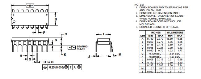
TL494 Package

TL494 Package

TL494 Manufacturer

On Semiconductor (Nasdaq: ON) is a manufacturer engaging itself in reducing energy use. It features a comprehensive portfolio of power, signal management, and logic, custom solutions that are energy efficient. It acts as a world-class supply chain with high reliability and a network of manufacturing facilities, sales, offices, and design centres in key markets through North America, Europe, and the Asia Pacific regions.

Datasheet PDF

TL494CNG Documents

Download datasheets and manufacturer documentation for TL494CNG

Frequently Asked Questions

What is the use of TL494?
TL494 is a PWM controller IC used for power electronics circuits. It comprises of on-chip two error amplifiers an oscillator with adjustable frequency feature, an output flip-flop having pulse steering control, and an output control circuit with feedback.
How does a PWM IC works?
As its name suggests, pulse width modulation speed control works by driving the motor with a series of “ON-OFF” pulses and varying the duty cycle, the fraction of time that the output voltage is “ON” compared to when it is “OFF”, of the pulses while keeping the frequency constant.
What is a PWM circuit?
Pulse Width Modulation, or PWM, is a digital technique to enable the proportional control of analogue devices more efficiently. ... The digital nature (fully on or off) of a PWM circuit is less costly to fabricate than an analogue circuit that does not drift over time.
FAQ
What is the use of TL494?
TL494 is a PWM controller IC used for power electronics circuits. It comprises of on-chip two error amplifiers an oscillator with adjustable frequency feature, an output flip-flop having pulse steering control, and an output control circuit with feedback.
How does a PWM IC works?
As its name suggests, pulse width modulation speed control works by driving the motor with a series of “ON-OFF” pulses and varying the duty cycle, the fraction of time that the output voltage is “ON” compared to when it is “OFF”, of the pulses while keeping the frequency constant.
What is a PWM circuit?
Pulse Width Modulation, or PWM, is a digital technique to enable the proportional control of analogue devices more efficiently. ... The digital nature (fully on or off) of a PWM circuit is less costly to fabricate than an analogue circuit that does not drift over time.

TAGS

Share