
Introduction
What is a voltage divider?
A voltage divider is an electronic circuit component typically comprised of two or more resistors. It is used to distribute input voltage to different output voltages or to reduce voltage in a circuit. The primary function of a voltage divider is to allocate the input voltage to multiple output nodes. It can also be utilized to decrease voltage in a circuit. In a voltage divider circuit, the output voltage is inversely proportional to the resistance, meaning that as the resistance increases, the output voltage decreases.
Voltage divider features
The main feature of a voltage divider is the ability to achieve different voltage distributions by changing the values of resistors. In addition, it also has the following characteristics:
- Simple to manufacture and low cost.
- Small in size, light in weight, and easy to carry.
- Widely applicable to various circuits.
- The output voltage in a voltage divider circuit is inversely proportional to the resistance.
Voltage divider principles
A voltage divider circuit is primarily composed of resistors and a power source. In the circuit, the positive terminal of the power source is connected to one end of the circuit, the negative terminal is connected to the other end, and the resistor is connected between the two ends. When the power source applies voltage, a voltage drop occurs across the resistor, and the voltage at the resistor's position is directly proportional to its resistance value. By connecting multiple resistors in the circuit, different voltage division ratios can be achieved.
When the power source applies voltage V, the magnitudes of voltages V1 and V2 can be calculated using the following formula:
V1 = V * R2 / (R1 R2)
V2 = V * R1 / (R1 R2)
Here, R1 and R2 represent the resistance values of the two resistors, and V1 and V2 are the voltages at the two ends of the circuit. It can be seen that the voltage division ratio is directly proportional to the ratio of resistances in the circuit.
Voltage divider formula
The Voltage divider formula is based on Ohm's Law and the characteristics of series circuits. According to Ohm's Law, current equals the ratio of voltage to resistance. In a series circuit, resistors are connected in series, and the division ratio is directly proportional to the resistance values. The voltage divider formula can be expressed as:
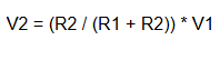
Here, V1 is the input voltage, V2 is the output voltage, and R1 and R2 are the resistance values of the two resistors. Using this formula, the output voltage can be calculated based on the ratio of resistances.
Voltage divider applications
1. Voltage Regulation
In circuit design, a voltage divider is commonly used to regulate voltage for voltage stabilization. In voltage regulator circuits, the voltage divider is often used as part of the feedback circuit to achieve high-precision voltage regulation. Voltage dividers can also be utilized in designing signal conditioning circuits to reduce the input signal levels for easier processing by subsequent circuits.
2. Voltage Detection
Voltage dividers are also frequently employed for voltage detection purposes. In automated control systems, measuring various voltage levels is necessary for control implementation. In such cases, a voltage divider can be used to attenuate the input voltage, facilitating subsequent measurement circuit processing.
3. Audio Processing
In audio processing circuits, adjusting the audio signal levels is essential. A voltage divider can be used to attenuate the audio signal levels for easier processing by subsequent signal processing circuits. For instance, in electronic musical instruments, voltage dividers are commonly used to adjust the volume of the sound.
RELATED TOOLS:
Reactance Calculator - a tool used to calculate the reactance of an electrical circuit component, such as a capacitor or an inductor.
Inductance Conversion - Inductance conversion refers to the process of converting inductance values between different units of measurement.