
Overview: DC-DC power electronics converters are essential to the offboard EV fast charging solutions. There are a variety of topologies of the converter, isolated and non-isolated, which will be dealt with in this technical article.
Source of the picture : EcoLife - Electric and Hybrid Cars
Topologies for DC-DC Conversion Stage
Electric cars have started to make their appearance for a sustainable economy, and the governments of all countries are investing heavily in research related to electric vehicles. DC-DC stage is a part of the electric vehicle charger following the ac-dc conversion stage. The dc-dc converter has to handle high power and provide a quality power supply to charge the batteries. The topology used has to be modular in structure, and it is preferable to have fewer components. When the number of components in a charger is minimal, it leads to reduced cost and size of the converter. Different converter topologies have been developed by researchers across the globe that serve one or the other purposes of a typical electric vehicle charger. These converter topologies are discussed as follows.
A. LLC resonant converter

Fig. 1. Topologies for isolated DC-DC power stage: LLC resonant converter. Source M. Safayatullah et al.
The LLC dc-dc converter shown in Fig. 1 is a suitable power electronics converter topology for electric vehicle chargers. The converter can regulate the output voltage when the load condition is light. Zero voltage switching can be achieved when a wide range of output voltage is needed. In addition, the converter can perform zero current switching for the rectifier diodes. Such action ensures that the diode recovery losses are minimized. An output capacitor is also added, which acts as a filter. The output voltage can be regulated smoothly by varying the converter's switching frequency. The transformer turns ratio can help change the gain of the converter. The resonant tank gain and switching bridge gain are equally crucial for changing the voltage gain.
The LLC dc-dc converter can operate in three different modes. The modes of operation depend on the comparative values of the switching frequency and resonant frequency. The most ideal of the three modes is when switching, and resonant frequencies are the same. The resonant tank has unity gain, which allows for the optimal operation of the converter. The other mode is when a buck or step-down operation is intended. In such a case, the switching frequency is more than the resonant frequency. The last mode is when a boost or step-up operation is needed. This case will have the switching frequency lesser than the resonant frequency.
B.Dual active bridge converter
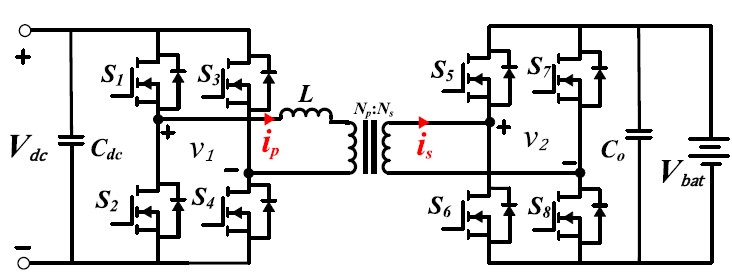
Fig. 2. Topologies for isolated DC-DC power stage: Dual active bridge converter. Source M. Safayatullah et al.
The Dual active bridge converter shown in Fig. 2 is an improvement over the earlier converter topology mentioned. As observed from the circuit, it consists of four switches at the input and output sides. The significant advantage of such an arrangement is that it allows for a bidirectional power flow between the input and output stages. The presence of a high-frequency transformer helps in galvanic isolation. This converter can provide a wide range of voltage transfer ratio. High efficiency and high power density are additional key features that are very useful for electric vehicle charging applications.
The bidirectional power flow between the input and output occurs thanks to the phase shift angle. A positive phase shift angle between the input and output leads to power flow from the input to the output. On the other hand, a negative phase shift angle between the input and output ensures power flow from the output to the input. Hence, bidirectional flow is possible with just a change in the polarity of the phase shift angles. Hence, controlling a dual active bridge converter is more straightforward than many other dc-dc converter topologies for electric vehicle charging applications.
The dual active bridge converter operates with three different switching modulation techniques. The most simple of the three is called the single-phase shift technique. This modulation technique uses only the phase shift angle as a variable for the bidirectional flow of power. But the drawback of this modulation technique is noted when applied to a light to medium load where zero voltage switching is difficult to achieve.
A better switching modulation technique is the dual-phase shift technique. The two variables considered in this technique are phase shift angle and single duty ratio. The single duty ratio refers to the duty ratio of any one of the bridges used in the power electronics converter. The feature of this technique is that the range of zero voltage switching is extended. However, all eight switches of the converter can secure zero voltage switching.
The triple-phase shift technique is the last and most advanced switching modulation technique. The three variables considered in this technique are the phase shift angle and the two individual duty ratios of both bridges of the converter. This technique secures zero voltage switching for all eight switches at no load conditions. But the drawback is that the turn-off current increases, resulting in switching losses.
C.Dual active bridge resonant converter
The performance of the dual active bridge converter with improved modulation scheme, as seen in the previous case, can be further improved using resonant tanks. Resonant tanks are suitable for attaining a wide zero voltage switching range. There are a variety of resonant tank circuits available. The most simple resonant tank circuit can be an LC circuit, and further reactive components can be added to improve their performance. As such, there are advanced resonant tank circuits such as CLC, LLL, LCL, and CLLC.
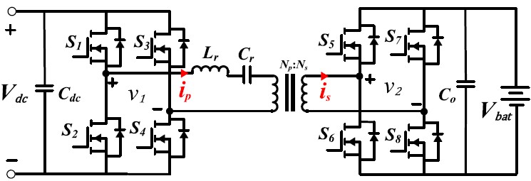
Fig. 3. Topologies for isolated DC-DC power stage: Dual active bridge series resonant (LC) converter. Source M. Safayatullah et al.
Fig. 3 illustrates the dual active bridge series resonance circuit with an LC resonant tank circuit. Such a structure is the simplest one and has fewer resonant components. The transformer has its leakage reactance which can be used as a series inductor of the tank circuit. In addition, the presence of a capacitor blocks any dc component. A drawback of this converter is that it suffers from hard switching when operating under certain regions of operation.
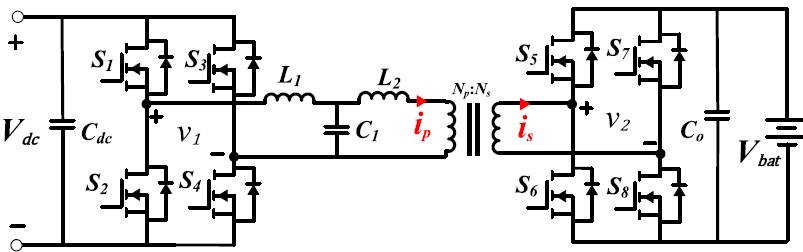
Fig. 4. Topologies for isolated DC-DC power stage: Dual active bridge converter with LCL resonant tank. Source M. Safayatullah et al.
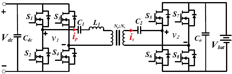
Fig. 5. Topologies for isolated DC-DC power stage: Dual active bridge converter with CLC resonant tank. Source M. Safayatullah et al.
Fig. 4 and Fig. 5 show dual active bridge converters with LCL and CLC resonant tanks, respectively. The currents in the bridges are found to be sinusoidal in these converters. The voltage and current waveforms are also in phase with each other. This applies to each of the individual bridges as well. Hence, the efficiency of the converter is higher because of the near elimination of reactive power. The CLC structure can handle higher power density out of these two resonant tank structures. Even with these improved resonant tank circuits, the converter is unable to secure soft switching when the battery voltage has a wider range. A modified version of these converters is shown in Fig. 6, which has a CLLC tank circuit. This new resonant tank circuit enables soft switching for battery voltage that is wider in range.
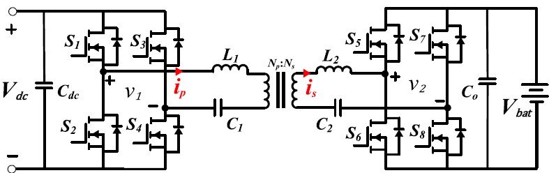
Fig. 6. Topologies for isolated DC-DC power stage: Dual active bridge converter with CLLC resonant tank. Source M. Safayatullah et al.
A common drawback with all the proposed resonant tank based dual bridge converters is that they demand complex mathematical modeling. Achieving synchronization is another issue that is possible with a complex control method. As these tank circuits attain asymmetrical voltage levels, paralleling operation is yet another issue with these converters.
D. Phase-shifted full-bridge converter

Fig. 7. Topologies for isolated DC-DC power stage: Phase-shifted full-bridge converter. Source M. Safayatullah et al.
The switches on the secondary side of the dual active bridge converters are replaced with diodes in the phase-shifted full bridge converter, as shown in Fig. 7. The replacement with diodes means that the power flow will be only unidirectional as diodes are uncontrolled devices. Such a converter has simple PWM control owning to the elimination of control on the secondary side. Soft switching can be attained on the primary side, and the current stress is reduced on the primary side. This structure is highly modular, and several modifications can be carried out by stacking several such converters.
There are numerous drawbacks associated with this converter as well. During the freewheeling period of the converter, a circulating current is seen on the primary side, leading to power loss. The cost of the converter is increased due to the presence of a large inductor on the secondary side. It also results in a reduced power density. Apart from this, the diodes on the secondary side undergo hard switching, which adds to the existing losses in the converter.
E. Non-isolated DC-DC converter
The non-isolated dc-dc converters are applicable for EV chargers where isolation from the mains is provided through a line-frequency transformer. A buck converter is a preferred topology because the voltage of the EV battery is less than that of the input voltage from the line. A fundamental drawback of the conventional buck converter is that it has high current ripples at the input of the dc-dc stage. These high ripples lead to higher charge and discharge cycles. Such a higher number of charge-discharge cycles directly increases the aging of batteries. These ripples can be reduced thanks to a large inductor at the input. However, a large inductor increases the size and cost of the converter. The power density is also reduced. The presence of only a single switch leads to a limited power handling capacity of the converter. The semiconductor switching losses are also high because the switch is directly connected to the input.
To overcome these drawbacks, interleaved buck converters are an improved solution. These converters have multiple numbers of inductors and switches. The many inductors reduce the ripples in the input current significantly. They can handle higher power, and their ability to develop modular structures makes them a versatile choice. The family of buck converters is shown in Fig. 8, Fig. 9, Fig. 10, and Fig. 11.
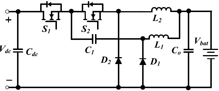
Fig. 8. Topologies for non-isolated DC-DC power stage: Interleaved two-phase buck converter. Source M. Safayatullah et al.
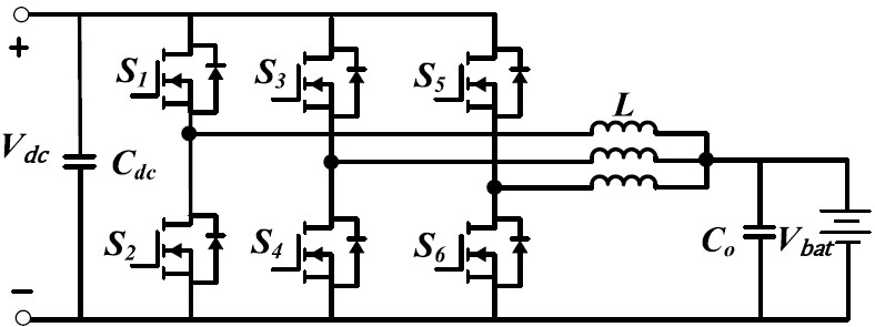
Fig. 9. Topologies for non-isolated DC-DC power stage: Interleaved three-phase buck converter. Source M. Safayatullah et al.
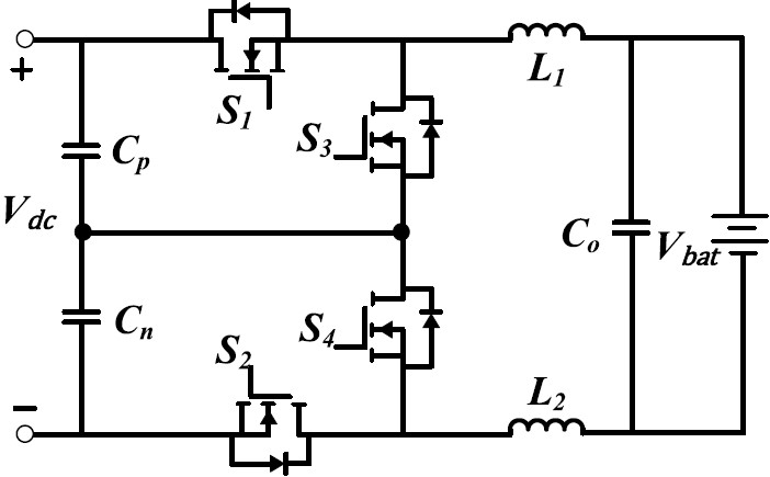
Fig. 10. Topologies for non-isolated DC-DC power stage: three-level buck converter. Source M. Safayatullah et al.
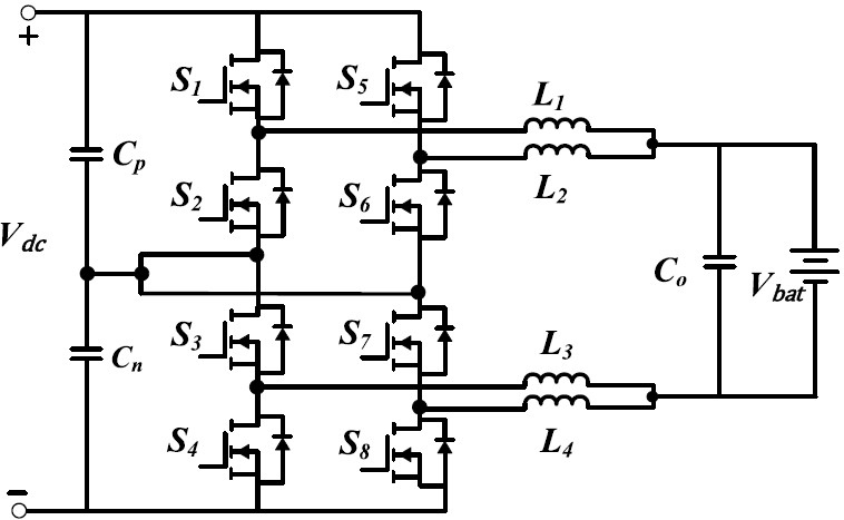
Fig. 11. Topologies for non-isolated DC-DC power stage: parallel three-level buck converter. Source M. Safayatullah et al.
Summarizing with key points:
- DC-DC converter topologies are an important component of fast chargers in electric vehicles to provide high-quality dc voltage to charge the batteries.
- These converters can be broadly classified into isolated and non-isolated topologies. In many practical applications, isolated topologies are preferred for their ability to provide galvanic isolation.
- The resonant converters are isolated converters that feature soft switching capabilities and operate at a very high switching frequency. However, operating at a resonant frequency under all circumstances requires very accurate control of converters.
- Dual active bridge converters are also isolated converters that can achieve soft switching for a wide range of battery voltage. However, circulating currents during a freewheeling operation lead to semiconductor switching losses.
- Phase-shifted full bridge converters replace switches in the previous two converters with diodes. Such an arrangement helps in simpler control using PWM, but the diodes undergo hard switching, which causes power loss.
- The buck converters are non-isolated ones, used when a line frequency transformer exists before the ac-dc stage for galvanic isolation. These converters are usually employed less than the non-isolated ones because of their increased cost and size due to the line frequency transformer.
Future Trends ahead:
- Ultra-fast chargers can charge a typical Electric Vehicle battery in 10 to 15 mins. However, the dc-dc converter topologies are still in the nascent stage, and they have high potential.
- Partial power converters are gaining popularity where only a fraction of the full power is utilized. It results in reduced size and cost of the converter.
- Vehicle-to-grid and Vehicle-to-home are two promising areas of research where bidirectional converter topologies can be exhaustively analyzed and built.