
Executive Summary
When a Product Discontinuance Notification (PDN) arrives for a microcontroller (MCU) on an active vehicle program, engineering and sourcing teams must execute a three-step triage sequence within 14 days: calculate total lifetime component demand across remaining production and post-production service tails, evaluate software coupling and Automotive Safety Integrity Level (ASIL) constraints to select an engineering mitigation branch, and issue non-cancellable, non-returnable (NCNR) bridge or Last-Time-Buy (LTB) purchase orders before factory production allocation slots freeze.
1. Why EOL Now Arrives Mid-Program
Semiconductor foundries are systematically reallocating mature-node wafer capacity (90nm, 65nm, and 40nm planar nodes) toward high-margin compute and AI silicon. Advanced semiconductor manufacturing equipment carries lead times of 18 to 24 months. Decisions made today yield no output before late 2027. Consequently, foundries are choosing not to replace aging tooling on mature lines. Rather than enjoying a natural end-of-life aligned with vehicle platform retirement, established MCU families are appearing on discontinuation notices partway through active vehicle production cycles.
Observable market symptoms highlight this structural allocation shift: extended STMicroelectronics 90nm MCU lead times (≈55 weeks in early 2026), Texas Instruments price increases effective April 2026, and continuous allocation pressure on mature-node MCUs from NXP, Renesas, and Infineon illustrate the structural shift that expands the lifecycle gap in managing semiconductor obsolescence in automotive ECUs[3].
Mid-program EOL is now a standard operational event to plan for across every multi-year vehicle architecture.
2. Anatomy of an Automotive PCN/PDN: Reading the Notice Correctly
When a supplier issues a Product Change Notification (PCN) or Product Discontinuance Notification (PDN), reading the document parameters accurately determines your team's operational timeline.
[ PDN Issued ] ───► [ Last Time Buy (LTB) Date ] ───► [ Last Time Ship (LTS) Date ]
Day 0                ~6 Months Out                     ~12 Months Out
(Decision Window:      (Hard Order Deadline)             (Factory Shut)
Days 1–14)
Anatomy of a standard PDN:
- Last Time Buy (LTB) Date / Last Order Date: The final calendar date the semiconductor manufacturer accepts binding purchase orders. Beyond this date, wafer start allocations for the part are permanently closed.
- Last Ship Date (LTS): The final date manufacturing and logistics will dispatch fulfilled orders from distribution centers.
- Vendor Commitments: The notice binds the vendor to deliver orders accepted prior to the LTB date, provided factory capacity remains unconstrained. It does not guarantee order adjustments or delivery schedule extensions.
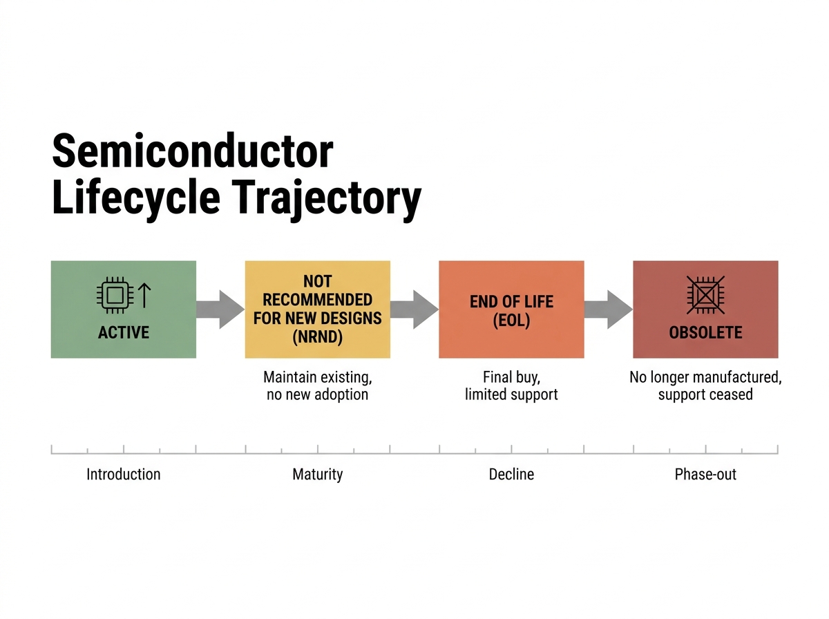
Lifecycle status definitions are frequently conflated, leading to misallocated engineering resources:
- NRND (Not Recommended for New Designs): The part remains in full volume production. The vendor discourages new design-wins, often signaling that fab capacity is constrained or a node migration is planned. Action: Initiate long-term alternative evaluation; do not panic-buy.
- EOL / PDN (End of Life / Product Discontinuance): The component is officially entered into its phase-out window under the vendor's official Product Change Notification (PCN) process[1]. The fab line has a fixed termination date. Action: Execute immediate LTB math and qualification planning.
- Obsolete: Production has permanently ceased. Distribution channels no longer hold factory stock. Action: Source through certified open-market stock or execute an emergency redesign.
Although the nominal window between notice and last order date is commonly six months[4] (with shipments extending up to twelve months out), the practical decision window is roughly 14 days. Internal capital allocation approvals, contract negotiations with the OEM customer, and technical requalification lead times consume nearly the entire buffer.
3. The First-Two-Weeks Decision Tree
Selecting the wrong mitigation path during the initial 14-day window creates multi-million dollar liabilities in excess inventory or unscheduled assembly line shutdowns. Evaluate candidates against program lifecycle parameters:
| Strategy Branch | Remaining Program Life | Annual Build Volume | ASIL & Safety Relevance | Software Coupling Level | Primary Action Trigger |
|---|---|---|---|---|---|
| Branch 1: Last-Time Buy (LTB) | < 24 Months | Low to Medium | Any (ASIL A through D) | High (Custom HAL/MCAL, complex register interaction) | Board redesign Non-Recurring Engineering (NRE) and recertification costs exceed inventory holding costs. |
| Branch 2: Same-Family Drop-In | > 24 Months | Medium to High | ASIL A / B | Low to Medium (Standard AUTOSAR MCAL) | Pin-compatible sibling MCU exists with matching pinout and identical silicon process stepping. |
| Branch 3: Cross-Vendor Migration | > 36 Months | High | ASIL B / C | Medium | Sibling MCU unavailable; functional equivalent exists; core software architecture is portable. |
| Branch 4: Complete ECU Redesign | > 48 Months | High | ASIL C / D | High | Silicon architecture is fully abandoned; respin allows consolidating adjacent legacy ECUs. |
4. Last-Time-Buy Math: Model, Calculation, and Hidden Carrying Costs
Calculating Last-Time-Buy volume requires a strict formulaic approach. Never estimate LTB requirements by applying arbitrary percentage markups to annual build rates.
LTB Qty = [(Remaining Production Months × Monthly Build Rate) × (1 Line Yield Loss %) × (1 Field Return Rate %)] Service Parts Obligation Safety Stock
Worked Numeric Example
Consider an active Tier-1 Body Control Module (BCM) program facing an MCU EOL notice:
- Remaining Production Months: 24 months
- Monthly Build Rate: 10,000 units/month
- Line Yield Loss (Scrap): 1.5% (0.015)
- Field Return Rate (Warranty): 0.5% (0.005)
- Service Parts Obligation: 12 years post-EOP at 500 units/year
- Safety Stock: 3 months of baseline production (30,000 units)
Step-by-Step Calculation:
- Baseline Active Production Volume:
24 months × 10,000 units/month = 240,000 units - Yield Loss & Warranty Adjustment Factor:
1 0.015 0.005 = 1.020 - Adjusted Active Production Volume:
240,000 units × 1.020 = 244,800 units - Post-EOP Service Parts Obligation:
12 years × 500 units/year = 6,000 units - Safety Stock Reserve:
3 months × 10,000 units/month = 30,000 units - Final LTB Purchase Order Volume:
244,800 6,000 30,000 = 280,800 units
The Automotive Service Tail Multiplier
Industrial EOL guides routinely fail in automotive applications because they omit post-End of Production (EOP) service commitments. Master Service Agreements (MSAs) with automotive OEMs mandate component availability for 10 to 15 years[3] after the final vehicle rolls off the assembly line.
While active vehicle production in the example above requires 244,800 units, low-volume service part obligations over a 12-year tail add thousands of dedicated units. If the vehicle program life was only 12 months remaining, the service parts tail would represent over 30% of the total component order. This long-tail commitment makes automotive LTB capital commitments significantly larger than industrial equivalents.
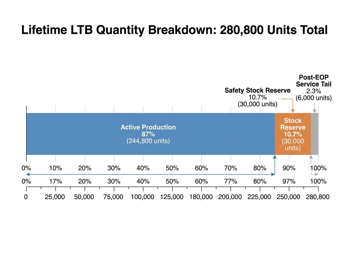
Active Production (24 Months): [==========================] 244,800 units
Safety Stock Reserve:          [===] 30,000 units
Post-EOP Service Tail (12 Yrs):[==] 6,000 units (Spans 10–15 year OEM contract obligation)
Hidden Carrying Costs and Warehousing Risks
Procurement teams frequently underestimate the true cost of holding multi-year LTB stock:
- Moisture Sensitivity Level (MSL) Degradation: Surface-mount MCUs rated at MSL 3 or higher absorb atmospheric moisture. Storage beyond 12 months requires vacuum sealed dry-packing with desiccants under IPC/JEDEC J-STD-033 standards. Prior to SMT assembly, aged stock must undergo high-temperature baking (typically 125°C for 5 to 48 hours) to prevent package popcorning and delamination during reflow.
- Lead Solderability & Leadframe Oxidation: Matte tin (Sn) leadframe finishes undergo intermetallic compound growth and surface oxidation over extended storage. After 3 to 5 years, lead wettability decreases, increasing IPC-A-610 soldering defect rates.
- Capital and Insurance Costs: A single multi-year LTB transaction ties up cash flow during periods when memory and passive component price inflation is already expanding the Bill of Materials (BOM). Insurance premiums for high-density warehouse storage of sensitive semiconductor inventory add annual overhead costs.
5. Cross-Reference Traps: Why "Pin-Compatible" Is Never "Drop-In"
Stating that an alternative MCU is "pin-compatible" addresses physical printed circuit board (PCB) footprint alignment, but it guarantees nothing regarding functional execution, timing, or safety compliance. Automated parametric cross-reference tools must never be used unsupervised for safety-critical (ISO 26262) automotive ECUs.
[ PCB Footprint Match ]  !=  [ Functional Execution Match ]
- Package & Pin Alignment     - Register Instance Offsets
- Power & Ground Pins         - ADC Conversion Topology
- Oscillator Tolerance (-40°C to  125°C)
- FMEDA & Safety Manual Assumptions
11-Point Engineering Verification Checklist
Before accepting an equivalent MCU as a candidate replacement, embedded engineering teams must verify eleven technical parameters:
- Flash and RAM Sector Geometry: Differing sector erase sizes alter internal flash writing algorithms, EEPROM emulation routines, and Unified Diagnostic Services (UDS) bootloader routines. Execution wait states at maximum clock frequency may alter timing loops.
- Peripheral Instance Offset Mapping: Peripheral base addresses and control registers differ between silicon families, breaking direct register writes in non-abstracted driver code.
- Interrupt Vector Table Layout: Priority schemes, nesting logic, and vector table offsets shift, risking priority inversion or unmapped interrupt traps in Real-Time Operating Systems (RTOS).
- ADC Architecture and Reference Voltage: Successive Approximation Register (SAR) architectures differ in sampling capacitance, input impedance, and conversion speed. Reference voltage drift across temperature alters analog sensor calibration maps.
- Internal Oscillator Tolerance: Factory-calibrated internal RC oscillators may drift beyond tolerance limits across automotive temperature ranges (-40°C to 125°C/ 150°C), causing CAN-FD bit-timing errors or LIN bus synchronization failures.
- AEC-Q100 Temperature Grade: Substituting an AEC-Q100 Grade 1 part ( 125°C ambient) with a Grade 2 part ( 105°C ambient) causes thermal shutdown or parametric drift in under-hood ECUs.
- Package Thermal Resistance (θJA, θJC): Changes in exposed pad dimensions or die size alter thermal dissipation paths, causing thermal throttling under full processor loads.
- Silicon Errata List: Replacement silicon carries distinct hardware errata that may invalidate established software workarounds implemented for the original chip.
- Functional Safety Documentation (ISO 26262): Hardware safety metrics—including Single Point Fault Metrics (SPFM) and Latent Fault Metrics (LFM) in the FMEDA—must match or exceed original values to maintain ASIL ratings.
- AUTOSAR MCAL and Vendor Driver Maturity: Microcontroller Abstraction Layer (MCAL) drivers for the new silicon may exhibit bugs or lack full AUTOSAR release compliance, forcing custom driver modifications.
- Compiler Toolchain and Flashing Compatibility: Toolchain transitions (e.g., GCC to HighTec or IAR) alter compiler optimization flags, code size, and stack usage profiles.
EOL Resistor Wiring Explained (End-of-Line Basics Made Simple)
The Hidden Software Driver Cost Trap
Low-level driver migration routinely represents the largest hidden expense when switching MCUs mid-program. Re-verifying MCAL driver interfaces, updating complex timing loops (such as PWM control for motor drives), re-qualifying bootloaders, and re-running software regression testing often costs twice as much as the physical PCB layout respin.
6. Requalification Scope: AEC-Q100, ISO 26262, and PPAP Matrix
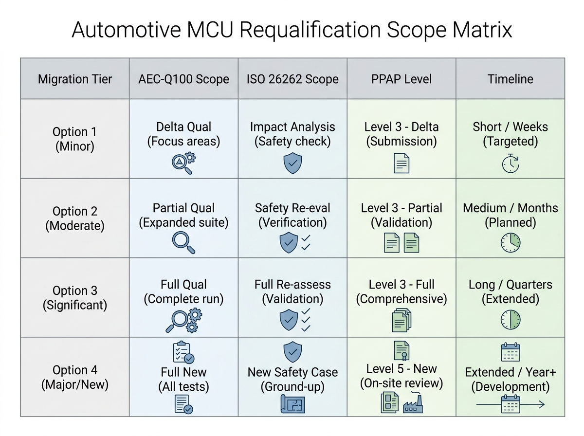
Changing an MCU on an active automotive program requires re-submitting Production Part Approval Process (PPAP) documentation[2] to the OEM customer under IATF 16949 standards. The required scope depends on the depth of silicon and hardware modification:
| Migration Scope | AEC-Q100 Test Groups Likely Affected | ISO 26262 Work Products Requiring Update | PPAP Submission Level Typically Requested | Realistic Elapsed Time |
|---|---|---|---|---|
| 1. Same Family, Memory Sizing Change (e.g., 512KB to 1MB Flash) | Group C (Package Assembly), Group E (Electrical Verification) | Software Safety Analysis, Test Execution Reports | Level 3 (Delta documentation: ESD, EMC, Flash verification) | 2 to 4 Months |
| 2. Same Vendor, Sibling MCU Family (Pin-compatible alternative) | Group A (Accelerated Environment), Group E (Electrical), Group F (Defect Screening) | Safety Case Delta, Hazard Analysis Review, Hardware-Software Interface (HSI) | Level 3 (Full Delta Test Results, updated FMEDA) | 6 to 9 Months |
| 3. Different Vendor Equivalent Silicon (Cross-vendor migration) | Full Qualification: Groups A (Environmental), B (Lifetime), C, D (Die Fab), E, F | Complete Safety Case Revision, FMEDA Re-calculation, Software Safety Verification | Level 3 or Level 5 (Full Customer Sign-off & On-site Audit) | 9 to 14 Months |
| 4. Complete ECU Board Redesign (New architecture) | Full AEC-Q100 Stress Testing Module Level Design / Process Verification (DV/PV) | Complete ISO 26262 Lifecycle (Item Definition through Safety Validation) | Level 3 / Full Production PPAP Package | 12 to 24 Months |
Note: Final requalification requirements are negotiated directly with the Tier-1 quality lead and the OEM customer. This table serves as an engineering planning baseline.
7. Sourcing EOL Automotive Parts on the Open Market
When factory Last-Time-Buy windows have closed or bridge stock is required to keep a line running during a redesign, sourcing components from independent distribution becomes necessary. Genuine parts are not automatically acceptable parts for automotive production.
[ Grey Market Reel ] ──► Solderability Decay? ──► SMT Wetting Failure
──► MSL Moisture Gain?   ──► Package Popcorning
──► Missing Traceability? ──► IATF 16949 Audit Breach
IATF 16949 quality traceability expectations do not relax because a component is obsolete. Eight-year-old genuine factory stock held under unmonitored warehouse conditions can fail solderability standards or suffer internal moisture absorption, causing package cracking during high-temperature SMT reflow.
6-Point Independent Supplier Demand Checklist
When issuing purchase orders for obsolete or allocated automotive MCUs outside authorized channels, mandate the following deliverables from the supplier:
- Documented Supply Chain Provenance: Complete, unbroken lot traceability records tracing back to the original fab, assembly site, or authorized distribution channel.
- Original Packaging and Dry-Pack Inspection: Verification that parts remain in original factory reels, with intact vacuum sealing, desiccants, and active Humidity Indicator Cards (HIC).
- Pre-Purchase Date Code Disclosure: Written confirmation of manufacturing date codes before issuing purchase orders to evaluate age-related lead oxidation risk.
- Certified Test and Inspection Reports: Independent lab verification following AS6081 and CCAP-101 standards, including visual inspection, X-ray inspection (leadframe integrity), decapsulation/die verification, and full electrical parameter testing across temperature extremes.
- MSL Re-Bake Documentation: Certified baking and re-vacuum sealing records following IPC/JEDEC J-STD-033 protocols if the original moisture barrier bag integrity is compromised.
- Legally Binding Warranty Terms: A written, 365-day quality return agreement that guarantees complete credit or replacement if components fail incoming quality control or automated optical inspection (AOI) on the SMT line.
Navigating these requirements requires sourcing partners who maintain rigorous quality infrastructure. Tier-1 suppliers can manage these risks by utilizing authorized manufacturer component channels[5] to secure hard-to-find components backed by anti-counterfeit verification, full IATF-level supply chain traceability, incoming electrical testing, and flexible zero-MOQ bridge buy support. Furthermore, engineering teams can implement component selection and lifecycle monitoring platforms[6] to track active lifecycle statuses and identify NRND notifications long before factory allocations close.
8. A 90-Day Execution Plan
Managing an automotive MCU EOL notice mid-program requires immediate, concrete actions assigned across engineering, sourcing, and quality teams:
[ Days 1–14: Immediate Triage ] ──► [ Days 15–45: Feasibility ] ──► [ Days 46–90: Execution ]
- Lock Demand                       - Bench-Test Silicon               - Issue NCNR LTB Orders
- Run 11-Point Checklist            - Issue RFQs                       - Port MCAL Drivers
- Review OEM Contracts              - Submit PCN to OEM                - Submit PPAP Package
Days 1–14: Immediate Triage and Demand Freeze
- Procurement: Lock the active production build plan for the remaining program lifecycle. Calculate the preliminary LTB quantity using the mathematical model in Section 4.
- Engineering: Run candidate replacement parts through the 11-point cross-reference checklist. Identify whether a drop-in sibling MCU exists.
- Quality: Review the OEM Master Service Agreement to confirm exact service part obligation years (typically 10–15 years post-EOP). Log the PDN in the engineering lifecycle system.
Days 15–45: Technical & Commercial Feasibility
- Sourcing: Issue formal Requests for Quotation (RFQs) for factory LTB allocations or certified open-market bridge stock.
- Embedded Software: Bench-test sample silicon. Measure clock drift, ADC linearity, and evaluate the effort required to port AUTOSAR MCAL drivers or vendor HAL code.
- Quality: Submit preliminary customer notification of the upcoming silicon change to the OEM, proposing the qualification baseline and delta testing matrix.
Days 46–90: Execution and Qualification
- Procurement: Issue binding, non-cancellable, non-returnable (NCNR) purchase orders for the finalized LTB quantity or secure verified bridge inventory.
- Engineering / Software: Complete software driver modifications, update compiler toolchains, and run full regression tests on test benches.
- Quality: Complete delta AEC-Q100 stress testing, compile the Level 3 PPAP package, and submit final documentation to the OEM customer for formal sign-off.
Final Checklist: EOL MCU Triage Protocol
- [ ] Received PDN/PCN verified and logged in the engineering lifecycle management platform.
- [ ] Total LTB purchase volume calculated using production demand, yield loss, field returns, and post-EOP service obligations.
- [ ] 11-point cross-reference checklist completed for proposed replacement silicon candidates.
- [ ] ISO 26262 functional safety impact and ASIL safety case revisions evaluated with the safety manager.
- [ ] Delta AEC-Q100 qualification testing scope and PPAP submission level agreed upon with the OEM customer.
- [ ] Binding NCNR LTB purchase orders placed with the manufacturer or traceable open-market bridge stock secured under a 365-day quality warranty.
Sources and references used for this guide
- Microchip Product Change Notifications
Source type: official company documentation
Used for: Defining PCN/PDN timeline rules, NRND status, and formal EOL notification structures.
Caution: Vendor policy document; specific terms apply to Microchip product lines. - Texas Instruments Automotive PPAP & Reliability
Source type: official company documentation
Used for: Automotive PPAP submission levels and AEC-Q100 qualification standards.
Caution: Vendor quality policy; baseline reflects TI manufacturing processes. - Automotive IQ: Managing Semiconductor Obsolescence in ECUs
Source type: reputable professional source
Used for: Contextualizing the 10-15 year OEM service parts obligation tail vs shorter silicon node lifecycles.
Caution: Industry analysis article; specific OEM contractual terms vary. - J2 Sourcing Component Obsolescence Playbook 2026
Source type: vendor article
Used for: Standard operational timelines for LTB order dates (6 months) and LTS shipment dates (12 months).
Caution: Commercial distributor content; use for operational timeline bounds. - JAK Electronics Global Manufacturer Sourcing Network
Source type: official product page
Used for: Referencing independent distributor quality testing, MSL verification, and open market sourcing.
Caution: Publishing brand page. - 5 Must-Have Component Selection Platforms for Electronics Engineers
Source type: vendor article
Used for: Internal blog reference for component lifecycle tracking and selection tools.
Caution: Publishing brand internal content.