
Line filters help to suppress the generated radio-interference voltage. These can easily be designed from passive components such as current-compensated line chokes and X/Y capacitors. This article concerns the design of a single-phase line filter.
Switch-mode power supplies (SMPS) result in conducted interference because they generate radio-interference voltage on the mains side. This can interfere with other equipment supplied with mains power. Line filters help to suppress the generated radio-interference voltage. These can easily be designed from passive components such as current-compensated line chokes and X/Y capacitors. This article concerns the design of a single-phase line filter.
Parasitic current at the SMPS input
Parasitic currents result in radio-interference voltage via impedances. Figure 1 shows the main current flow of parasitic currents in an SMPS.
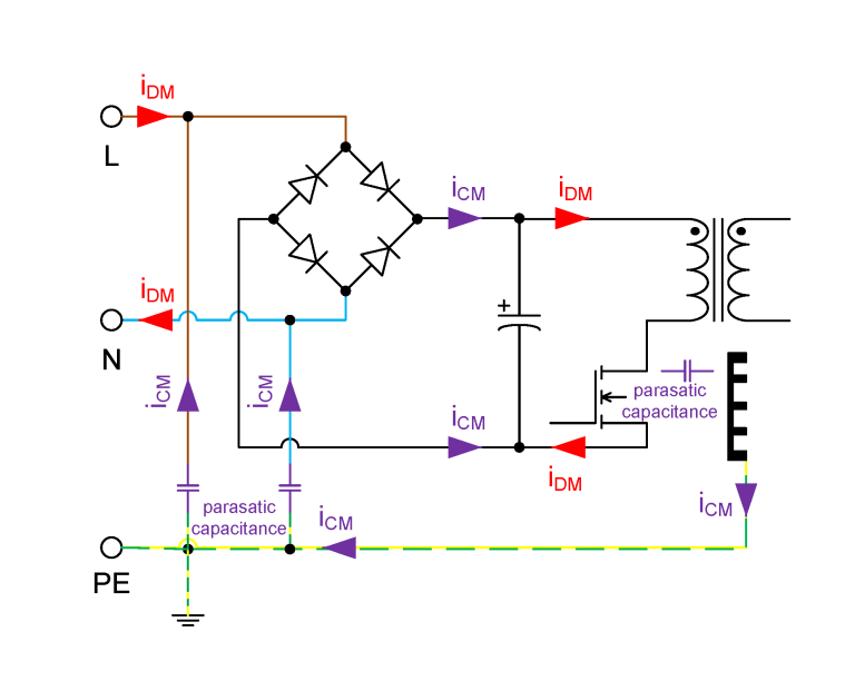
Initially, a high-frequency active current (iDM) flows on the mains side with the pulse frequency of the switching regulator, which results in differential-mode interference. Caused by fast-switching processes of semiconductor components, usually MOSFETs, high-frequency oscillations occur in combination with parasitic effects. In principle, the differential-mode current flows from the mains power line (L) over a rectifier bridge, then over the primary winding of the isolating transformer, over the MOSFET, and over the neutral conductor (N) back to the mains. The MOSFET is mounted on a heatsink for cooling. In turn, this is connected to the protective earth conductor (PE). Capacitive coupling between the heatsink and the drain of the MOSFET occurs here and produces common-mode interference. A capacitively coupled common-mode current (iCM) now flows along PE back to the SMPS input, where it is coupled again via parasitic capacitance both on L and N. The iCM now flows, as shown in Figure 1, over both mains power lines, via the rectifier bridge to the MOSFET, where it is again parasitically coupled via the heatsink to PE.
Expected interference spectrum
The rectified mains voltage is applied at the drain-source section. The peak level of the rectified mains voltage corresponds to:

An SMPS with a pulse frequency of 100 kHz has been used as an example. For this pulse frequency, the timing signal corresponds to T = 10 µs. The pulse duration is 2 µs. Based on this, the duty cycle can first be determined:
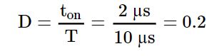
Assuming that the current through the rectifier bridge is trapezoidal, the EMC spectrum without line filter and without further Fourier transformation can be approximately determined. The first corner point of the enclosing amplitude spectral density is needed first:
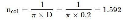
The first corner frequency of the enclosing amplitude spectral density is analogous to this:

The amplitude of the first harmonic can be determined from this:

Based on the assumption that the parasitic coupling capacitance (CP) between the SMPS and ground is 20 pF, the first harmonic common-mode current can now be determined:

The radio-interference voltage is measured using a line-impedance–stabilization network (LISN) and an EMC test receiver. Due to the parallel connection of the 50-Ω input impedance of the EMC test receiver and the 50-Ω output impedance of the LISN, a total impedance (Z) of 25 Ω is produced. The measured radio-interference voltage (VCM) can now be calculated:

Converted to decibel-microvolts, this gives:

The result of the calculation is that high interference emissions can be expected. For example, the product family standard EN 55022 can be used here for assessment of the interference emission. In the frequency range of 0.15 MHz to 0.5 MHz, it defines a permissible quasi-peak weighted interference level of 66 dBµV to 56 dBµV. Figure 2 shows the result of the measurement of the conducted radio-interference voltage of this SMPS without line filter.
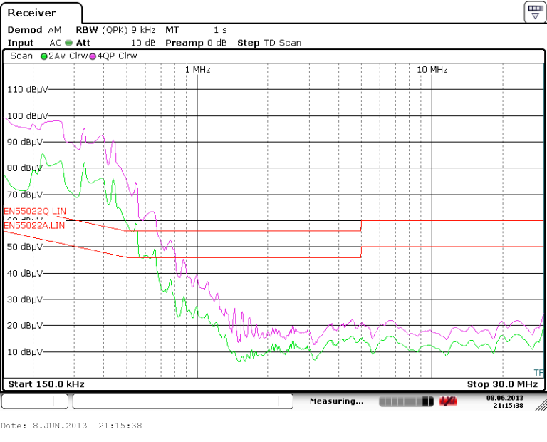
The measurement shows that a line filter is absolutely essential.
Design of a line filter
Figure 3 shows the schematic design of a simple single-phase line filter. Würth Elektronik provides various models of line chokes, such as the WE-CMB series, for the construction of line filters. A line choke basically consists of a manganese-zinc ring core, on which there are two geometrically separated windings wound in opposite directions. Figure 4 shows the design of the WE-CMB. In this case, the WE-CMB acts like a filter coil, which counteracts the current and reduces its amplitude. A common-mode choke with an as-low-as-possible self-resonance frequency (SRF) in the lowest-frequency range should be selected because the SMPS used here switches with very low pulse frequency. Low SRF causes high attenuation in the lower-frequency range.


Figure 5 shows the characteristic curve of the attenuation for the WE-CMB, size XS with 39-mH inductance, in the 50-Ω system.
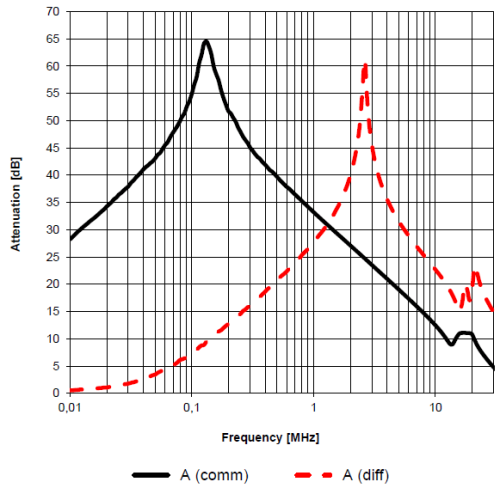
A distinction is always made in the attenuation between the common-mode (black line) and differential-mode (red, dashed line) suppression. In common-mode operation, the WE-CMB line choke reaches its maximum attenuation at 150 kHz. However, the attenuation drops with increasing frequency. Other X/Y capacitors are required because the line filter should suppress interference up to 30 MHz. An X capacitor is placed both before as well as after the line filter to block differential-mode interference from the mains side and the SMPS. With its leakage inductance, the WE-CMB in combination with the X capacitor forms a low-pass filter, which reduces the differential-mode interference and subsequent common-mode interference. Two X capacitors with a value of 330 nF have been selected here as an example. Their SRF is approximately 2 MHz.
For safety reasons, a resistor must be placed on the mains side in parallel with the X capacitor to discharge the capacitor if the SMPS is disconnected from the mains. A varistor should also be placed before the line filter so that transient overvoltages from the mains are short-circuited. Würth Elektronik disk varistors from the WE-VD series are ideally suitable for this. Overload protection such as a fuse must also be considered, and this should always be placed before the varistor. The protection trips in the case of a short-circuit by the varistor. Y capacitors are required for further suppression of the common-mode interference. In combination with the WE-CMB, they form a corner frequency (f0), which is defined by the Thomson oscillation equation:
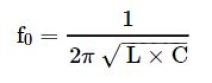
Attenuation of 40 dB is required to achieve levels below the permissible interference level of 66 dBµV (at 150 kHz). This corresponds to two decades in the logarithmic representation. One-tenth of the pulse frequency is used as a factor for the corner frequency or further calculation of the Y capacitors. The oscillation equation is now converted and used to determine the Y capacitance:

As two Y capacitors are needed, the calculated value is divided by 2. Y capacitors conduct common-mode interference from the SMPS back to PE. Depending on the device type, only leakage currents of 0.25 mA to ≤3.5 mA are permissible; no capacitance with a value greater than 4.7 nF should be used. Two Y capacitors with an E12 value of 2.2 nF have been selected for this reason. Figure 6 shows the result of the measurement with this line filter.
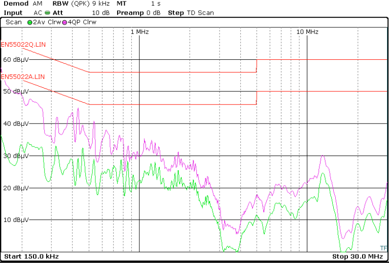
With the filter in circuit, the result of the radio-interference voltage test is a pass. The margin between the respective interference limits and the quasi peak and average measurements at the frequency of 150 kHz is greater than 10 dB, and this margin significantly increases across the frequency range.
Optimization of the line filter
It is also possible to further increase the signal-to-interference ratio in the lower-frequency range. Two X capacitors with 330 nF are replaced with two 1.5-µF X capacitors for this. Figure 7 shows the measurement of the optimized line filter.
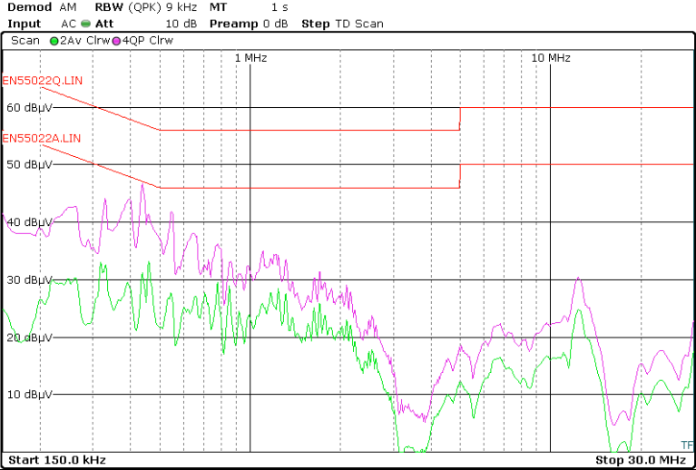
The change of the capacitance causes a reduction of the radio-interference voltage of approximately 15 dB in the lower-frequency range. A greater signal-to-interference ratio has been achieved and a good line filter designed.
Error due to dispensing with line choke
It is often tried at the beginning to only use X and Y capacitors to suppress interference in order to dispense with a common-mode choke. However, this is contrary to the principle of the line filter of counteracting the interference current by adding a high-impedance filter element. The radio-interference voltage using the same filter without common-mode choke has been measured as an experiment. Figure 8 shows the measurement.
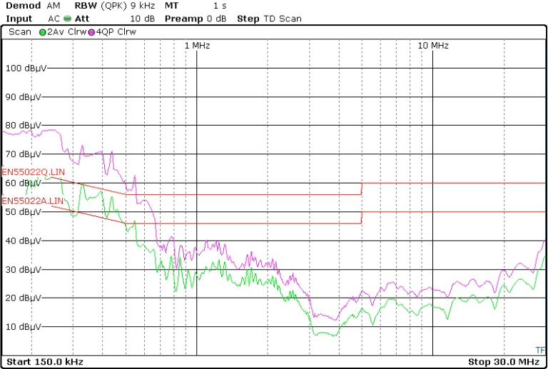
As expected, the interference emission in the lower-frequency range increases strongly without the WE-CMB line choke. At 200 kHz, the quasi peak shows a value of approximately 78 dBµV and the average shows a value of 60 dBµV. The permissible interference level is exceeded up to 600 kHz both by the quasi peak as well as by the average measurement. A line filter without a line choke is inadequate.
Additional differential-mode filter
If the differential-mode suppression using the WE-CMB and the X capacitors is not sufficient, an additional differential-mode filter consisting of two coils connected in series helps. Figure 9 shows the design.
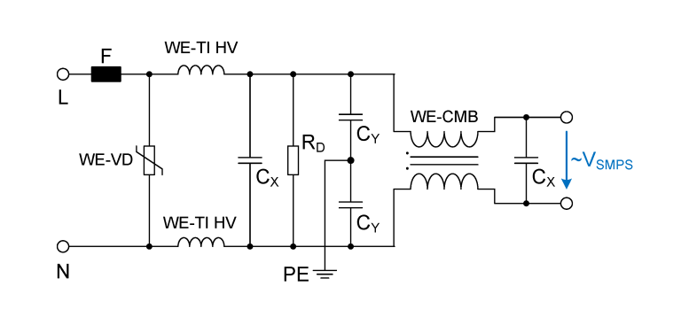
The Würth Elektronik coils WE-TI HV and WE-PD2 HV or the WE-SD series are ideally suitable for the differential-mode suppression. The WE-UKW series is recommended in the case of high-frequency interference. The Thomson oscillation equation can be used again here to calculate the coils. If attenuation of 40 dB/decade would be required from each coil, the calculation should be made with a corner frequency of one-tenth of the pulse frequency.
The already-used X value of the X capacitors can be used for the calculation of the coil:
As the coils for the differential-mode current are in series, the calculated value is divided by 2. The next larger inductance value of a WE-TI HV would be 470 µH. It should be ensured for the selection of a differential-mode coil that its rated current (IR) is far above the rated current of the SMPS input.
Result of the line filter
In conclusion, a line filter for switch-mode power supplies without a common-mode choke is not sufficient. Individual capacitors are not sufficient to completely suppress the interference emission. Additional longitudinal coils before the line filter help if further suppression of the differential-mode interference is required. Using a line filter, all interference levels are below the permissible limit value and the SMPS can pass an EMC test.