
The future of power electronics requires the evolution of modern energy-conversion systems to make them more efficient, cheaper, and smaller than their predecessors. Such systems require accurate current measurement. Open-loop Hall-effect sensors are often used for this purpose: A conductor produces a magnetic field comparable to the current that is then concentrated by a magnetic core and measured by the Hall sensor.
Recent introductions of custom ASIC solutions have helped to increase measurement accuracy. The evolution of ASIC technology has paved the way for the development of open-loop Hall-effect sensors that match the performance of closed-loop technology.
Open- vs. closed-loop sensors
Open-loop current sensors (Figures 1 and 2) consist of a Hall sensor mounted in the air space of a magnetic core. They measure both AC and DC and provide electrical isolation between the input and output sections, with the galvanic isolation ensuring non-contact measurement. The amplified Hall signal represents the sensor output. Open-loop sensors are usually less expensive than other options, and their low operating-power requirements and small footprint suit them for use in battery-powered circuits. Their disadvantage is that they can be prone to saturation and temperature drift.
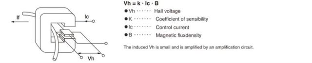
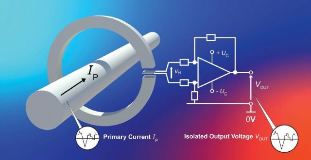
Figure 1 illustrates the principles behind the Hall current sensor. The magnetic flux produced in proportion to the primary current, If, induced in the magnetic circuit, passes through the Hall element inserted in the gap of the magnetic circuit, resulting in a potential difference, Vh, expressed by the formula shown in the figure.
Closed-loop current sensors offer fast response, high linearity, and low temperature drift, with low output noise, suiting them for applications requiring exact measurements. The closed-loop sensor takes the concepts of the open-loop version and adds a secondary winding to the output. The closed-loop device is sometimes called a “zero flux” sensor because it feeds an opposite current into a secondary coil, wound on the magnetic core, to zero the flux produced in the magnetic core by the primary current.
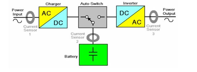
The output current of a closed-loop sensor is converted into a voltage value by connecting a resistor to the sensor output and ground. Selecting the resistor value may result in the output being resized.
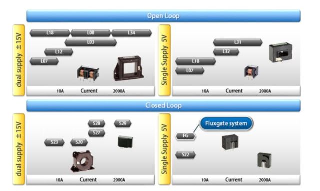
The choice of technology, whether open- or closed-loop Hall-effect or some other type, will largely depend on the particular constraints of the application (Figure 3).
LEM’s HMSR series
LEM’s new HMSR series of miniature integrated-circuit sensors for AC and DC isolated-current measurement can handle overload current bursts of up to 20 kA. LEM tailored the series to meet the market demand for cost reduction, performance improvements, and miniaturization. The sensors include a low-resistance primary conductor to minimize power losses and ensure ease of use. The sensor ASIC and ferrite magnetic element enable direct current measurements and maintain insulation performance.
The HMSR series uses a proprietary open-circuit Hall-effect ASIC combined with a single low-resistance primary conductor to minimize power loss, allowing measurement of direct current and high-transient-overload current without damage. Manufactured as SO16 surface-mount devices, they measure 6 mm high and can be mounted directly onto the PCB using the same process used for other board-level components, saving cost and space. An integrated E2PROM is used for internal temperature compensation and to counteract offset and gain drift through compensation.
The use of ferrite for the magnetic element enables a high-frequency bandwidth of 270 kHz (–3 dB) and provides excellent rejection against external fields, according to LEM. The mechanical design of the sensor results in dispersion and clearance of 8 mm when using materials with a comparative tracking index (CTI) of 600, allowing for reinforced insulation according to IEC 60950-1, the company said.
HMSR sensors’ unique primary conductor allows an overload of primary currents and a high level of insulation. The ferrite-based circuit provides the requisite immunity against the inhomogeneous fields present in various power electronics applications, such as solar panels. Built-in overcurrent detection (OCD) units separate the control application path to the safety loop. With two separate OCD units, the sensor can monitor overload and short-circuit events simultaneously.
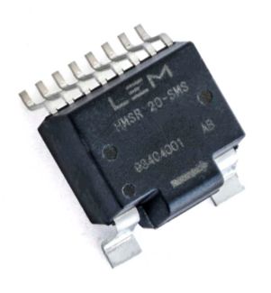
The protection and detection features of the HMSR series target HVAC or motor-driven applications. For solar-industry applications, which need to be surge-tolerant to provide adequate lightning protection, LEM has designed and tested the HMSR to deliver the required performance per the standard 8/20-μs surge test profile. LEM provides an HMSR evaluation board for quick prototyping and test (Figure 4).
TAMURA’s L32P series
Tamura produces current sensors based on Hall- and fluxgate-effect technology. The company states that the high accuracy and mechanical robustness of its open- and closed-loop products make it a world leader together with LEM and Honeywell in all industrial sectors. Driver modules complete the product range for driving silicon carbide (SiC) MOSFET/IGBT and DC/DC isolated converters.
Tamura’s solutions feature fast response times; high-frequency operation with minimal internal temperature rise; excellent dV/dt noise immunity; magnetic field stability; and sulfur-proof options, depending on customer application requirements (Figure 5).
The company’s L32PxxxS05(B)FS series of open-loop sensors uses a ferrite core for PCB mounting design. Heat generation due to high-frequency current is reduced with a wide electrical current range (saturation current of 150 to ~600 A).
The use of electronic controls for engine, transmission, and wheel speed control in vehicles and industrial systems continues to rise, driven by regulatory and market mandates to improve efficiency and safety. The control of these systems requires robust magnetic sensors that can operate reliably in harsh environments. A frequent challenge is the presence of common-mode noise and interference, which can limit measurement. Wear and tear on the gears can also lead to a reduction or loss of control signals.
The use of Hall sensors addresses these problems. Sensor performance can be significantly improved by incorporating them into a system and leveraging synergistic relationships as feedback and compensation.