
Climate change and society’s growing sensitivity to environmental issues require the development of technical solutions for fossil fuel-powered vehicles. Regulatory mandates for progressive reductions in emissions dictate the design of internal-combustion engines with lower volumes, higher engine revs, and the ability to operate with less rich fuel mixtures.
Those technological imperatives inevitably have implications for the operating conditions of insulated-gate bipolar transistors (IGBTs) used in engine ignition and control systems: The devices must attain higher clamping voltages and switching frequencies, with the attendant ability to dissipate excess heat. Here, we consider the effects on the thermal performance of IGBTs using different thermal PCB pads under different operating conditions.
IGBTs and thermal performance
The operating junction temperature (Tvj(op)) is fundamental to the operation of the device and should be considered as a practical value. When calculating the junction temperature for normal switching using conduction losses, switching losses, and thermal impedance, the junction temperature must always remain between the specified minimum and maximum values of Tvj(op) even in overload situations.
In practice, before the last switching event, the temperature of the joint must remain below Tvj(op) max. The transient temperature increases that result from switching losses in the switching event can be ignored, provided that the device is used within its safe operating area and that Tvj does not exceed Tvj max. Thermal management and cooling solutions are a growing concern for IGBTs because of increased heat loss in their application. Heat losses fall into two categories: conduction losses and switching losses.
Conduction losses occur during the switched-state voltage drop through the IGBT and depend on the current being conducted. The loss of switching power occurs during the switch-on and switch-off phases of the IGBT and is dependent on the current, operating cycle, switching voltage, and switching frequency.
Combustion engine’s evolution
New emissions regulations require substantial changes to the design of internal-combustion engines, including spark-ignition (SI) as well as the more efficient, compressed-ignition (CI) types.
To address the demand for more efficient, less polluting engines, vehicle manufacturers are following three basic strategies:
- Engine right-sizing and hybridization. These techniques resize the engine based on the class of the vehicle, maintaining the same power value. As a result, a higher number of revolutions is obtained, which in turn involves a higher switching frequency of the injection system and higher operating temperatures.
- Dilution of the mixture. This approach requires the use of wider gaps (necessary for proper heat dissipation) and higher voltages for triggering the spark plug. Therefore, it is necessary to use IGBTs with higher operating voltages.
- Direct injection during the compression stroke. This technique causes the formation of an area rich in combustible mixture near the spark plug, maintaining a poorer mixture globally. However, the high local and temporal variation that occurs around the spark plug risks compromising the injection system, designed to cover more space with longer ignition periods. This solution requires IGBTs with a very high breakdown voltage.
IGBTs used in ignition systems must therefore withstand high currents and have high clamping voltages under operating conditions that will inevitably produce a greater amount of heat.
In particular, IGBTs with a low collector-emitter ON voltage (Vce(ON)) value will be required so as to reduce power losses and junction temperatures.
Test procedure
To verify the effect on temperature of a low Vce(ON) value and to evaluate the impact on the thermal performance of an IGBT with different PCB pads, a simplified testbench can be used (Figure 1). Here, an inductance emulates the electrical characteristics of a commercially available ignition coil.
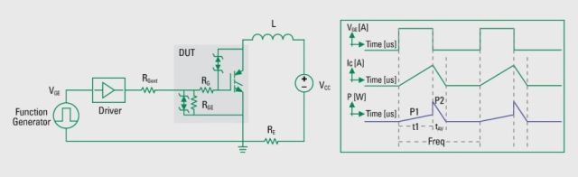
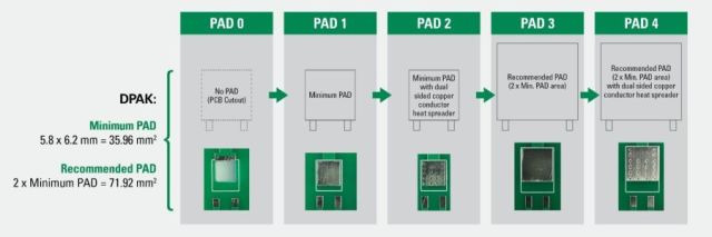
By varying the switching frequency and the dwell time, the device under test (DUT) is placed in correspondence with different types of pads made on the PCB (Figure 2) and kept operative for a time that’s sufficient to reach a stable temperature.
The test was conducted using a PCB with five types of pads, each with its own thermal conduction (Figure 2). More precisely, the test used:
- a pad in which there is no heat conduction path from the collector of the IGBT to the PCB (PAD 0);
- a pad with the same area as the IGBT package (PAD 1);
- a pad with the same area as the IGBT (PAD 2); and
- two pads with the recommended pad area for the specific device, without (PAD 3) and with thermal heat spreads from the top to the bottom of the PCB (PAD 4).
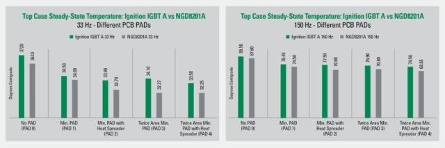
To quantify the improvement in thermal performance attributable to a lower Vce(ON), researchers compared the measurements obtained with a Littelfuse DPAK-packaged NGD8201A (Vce(ON) typ. <1.35 V) and those obained with a commercially available ignition IGBT (Vce(ON) typ. <1.5 V, labeled Ignition IGBT A in Figure 3).
frequencies and PCB pads (Image: Littelfuse)
The obtained results shown in the figure indicate that a slightly higher Vce(ON) results in a slightly higher steady-state temperature, regardless of the PCB pad used. As expected, this effect is more noticeable at high switching frequencies.
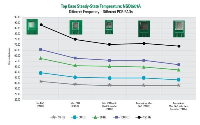
The effect produced by the use of different PCB pads is shown in Figure 4. The results indicate that higher switching frequencies result in higher steady-state temperatures. Of more interest is that PCB pads reduce the measured temperature, especially at high switching frequencies.
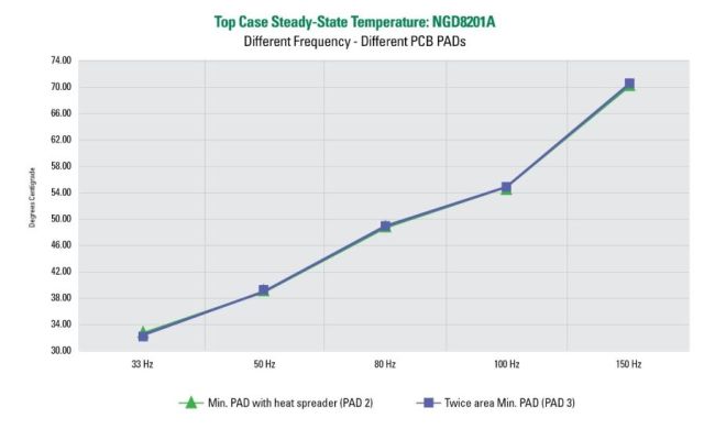
The plot obtained with the steady-state case temperature, under different frequencies, for PCB PAD2 and PAD3 (Figure 5) shows that the two pads offer the same average thermal dissipation capability. This result is relevant for ignition platforms, in which size is a crucial factor.