
Formula E, an electric-powered race car championship that began in 2014 and is currently known as “ABB FIA Formula E Championship” after ABB sponsorship in 2018, requires fully optimized power semiconductor modules, such as the latest generation of power converters.
This article, based on a presentation held at PCIM Europe Digital Days 2021 by Milad Maleki, project manager at Hitachi ABB Power Grids, focuses on the relevant role of high-density SiC power modules in Formula E, the most advanced and challenging competition for race electric vehicles (EVs). A detailed insight on the Hitachi ABB Power Grids RoadPak power module, successfully employed in Formula E, will be provided.
Formula E, an electric-powered race-car championship that began in 2014 and is currently known as “ABB FIA Formula E Championship,” after ABB sponsorship in 2018, requires fully optimized power semiconductor modules, such as the latest generation of power converters. Due to its competitive nature, Formula E includes specific requirements that cannot be found on commercial EVs. An example is the so-called attack mode, introduced some years ago to make races more spectacular and attractive. This feature, which can be activated when the vehicle crosses a specified track on the race circuit, provides an additional 35 kW of power to the motor for a certain time. The use of attack mode, monitored on the Halo device through a blue light indication, needs to be properly compensated during the race by energy management and requires a careful design of the involved power modules (PMs).
Formula E requirements
Being a competitive challenge, Formula E is mainly focused on achieving excellent performance from the PM during the championship, and therefore, requirements such as long-term reliability and cost have less importance than on commercial EVs. Power density (or current per unit surface), weight-to-power ratio, and immediate full-power availability are all mandatory requirements in Formula E. One advantage is that there is more flexibility in the inverter’s design, due to more relaxed volume production requirements and a more manual inverter assembly process. Moreover, cooling fluid selection and cooling characteristics can be more freely chosen, and there is a higher allowed pressure drop in the cooling system.
Design considerations
As in many other applications, Formula E silicon IGBT modules have been progressively replaced with silicon carbide MOSFET devices, considering SiC is a promising alternative technology. As an application in which low weight and enhanced efficiency are key factors, Formula E can benefit from the low losses of SiC MOSFETs in the design of inverters. The Hitachi ABB Power Grids RoadPak 1.2-kV SiC MOSFET half-bridge module, shown in Figure 1, includes in a small footprint (<70 × 75 mm) the latest-generation SiC MOSFET featuring low losses and high reliability to meet the increasing demand of the e-mobility market.
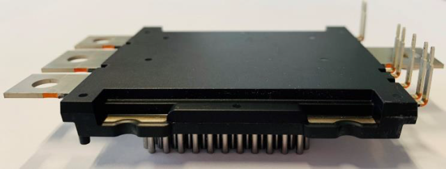
The RoadPak baseline design for the EV market is based on eight parallel SiC chips, which can be increased to 10 without changing the outline. This is the most practical solution, as increasing the active surface of individual SiC chips is limited due to yield challenges in their manufacturing (the active area of SiC MOSFETs currently in the market is less than 30 mm2). As confirmed by thermal simulation, connecting several SiC in parallel results in worse heat spreading and in an increase in thermal resistance (Rth) due to the thermal crosstalk between neighboring chips and the need to be carefully considered.
SiC MOSFETs shall be properly selected based on their conduction losses (Pcond), switching losses (Psw) at different switching frequencies, and, of course, reliability considerations. Conduction losses play the most relevant role in limiting the maximum current, which is a main function of the channel on-state resistance of the MOSFETs (RDS(on)) during conduction according to the formula Pcond ~ RDS(on) × Irms2. As a result, selection of a SiC MOSFET with the lowest possible RDS(on) is mandatory, although the lifetime tradeoff must be considered. Another advantage offered by SiC-based PMs is their low switching losses, including turn-on (Eon), turn-off (Eoff), and reverse-recovery losses (Erec). However, it should be noted that the higher the switching frequency, the higher the total switching losses in the power module. Besides RDS(on), maximum current depends on the maximum junction temperature TJmax. Therefore, it is necessary to select devices with higher TJmax and prioritize thermal management to decrease the Rth of the module. Whereas most of the SiC MOSFETs in the market are rated at a TJmax of 150°C to 175°C, the current RoadPak module is rated at 175°C and the trend is to increase the TJmax to 200°C.
Unlike commercial EVs, Formula E cars are not willing to operate in very low environment temperatures, and therefore, the coolant can include less glycol in a water-glycol mixture, with the benefit of lower viscosity and better cooling performance. Moreover, a coolant with lower viscosity decreases the pressure drop in the system, thus requiring a smaller and lighter pump. After a careful study, a serial one-side cooling with an optimized pin fin approach has been chosen for the RoadPak power module, a solution that provides high cooling performance and easy integration in the inverter.
In addition to the cooling scheme, thermal resistance is affected by design choices like die-attach materials and thickness, substrate ceramic type, and base plate design. For the RoadPak, a sinter die-attach material has been chosen due to its considerably higher reliability during power cycling, lower electrical resistance, and higher thermal conductivity. A thin and dense silver sintered layer for die attach (featuring a thermal conductivity of 320 W/mK) achieves a reduction of about 5% in thermal resistance in comparison with the soldering. Regarding the heat sink/base plate for the RoadPak design, copper has been preferred to aluminum–silicon carbide (AlSiC) due to its considerably higher thermal conductivity (385 W/mK for Cu, versus 180 W/mK for AlSiC) and better heat-spread effect. Modules with the copper base plate are usually expected to have a lower lifetime in passive power cycling due to their high coefficient of thermal expansion (CTE). However, by carefully selecting a mold compound that matches the effective CTE of the overall power module design, the negative impact of high CTE of Cu base plate has been effectively compensated in the RoadPak design. The power module layout requires particular attention in terms of electromagnetic design. To reach a high current rating and due to the small size of a SiC MOSFET, several SiC devices must be paralleled. The non-uniform switching that arises leads to increased oscillations and parasitic turn-on of a device. These undesired effects may also lead to current derating or limiting of the switching speed, thus reducing the low-loss advantages of SiC MOSFETs. The RoadPak 1.2-kV design for Formula E was optimized and the module was manufactured, aiming to reach the maximum possible power density. The validated Zth curve (transient temperature response to a unit power step) for the optimized 6Pak design is shown in Figure 2.
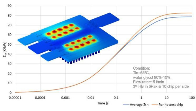
Thanks to the improvements on the PM thermal management and overall cooling system, an Rthmax of less than 83 K/kW was achieved for the conditions shown in Figure 2. The minor difference between the average Zth and the hottest chip Zth indicates the homogenous cooling of the parallel devices. The aforementioned low Rth allows an operating point of Irms > 900 A at the operating conditions (VDC = 800 V, f