
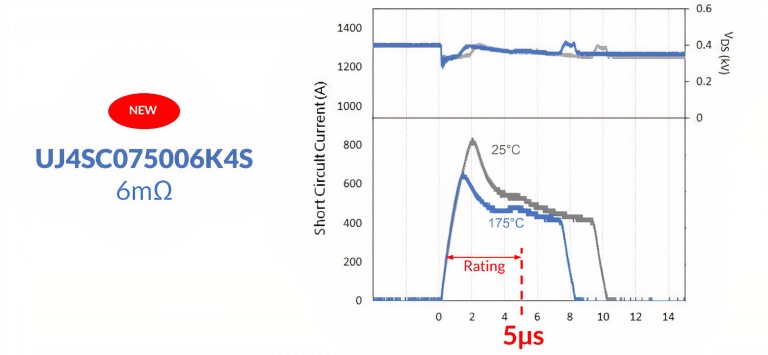
In response to designers’ needs for higher-performance, more efficient systems, UnitedSiC has announced new SiC FETs that enable new levels of design flexibility, most notably the solution from 750 V, 6 mΩ with a robust short-circuit withstand time rating of 5 μs.
In response to designers’ needs for higher-performance, more efficient systems, UnitedSiC has announced new SiC FETs that enable new levels of design flexibility, most notably the solution from 750 V, 6 mΩ with a robust short-circuit withstand time rating of 5 μs.
Anup Bhalla, vice president of engineering at UnitedSiC, said in an interview with Power Electronics News that achieving 6 mΩ for RDS(on) is unprecedented in the industry and that the set of 18- and 60-mΩ devices extended to 750 V gives designers more design flexibility to achieve an optimal cost/efficiency tradeoff while maintaining generous design margins and circuit robustness.
SiC FETs
UnitedSiC has developed SiC in a cascode arrangement for power electronics applications that require a normally off device (Figure 1). A power MOSFET is placed on top of the JFET in the cascode configuration, and the two are packed together for very low thermal resistance.
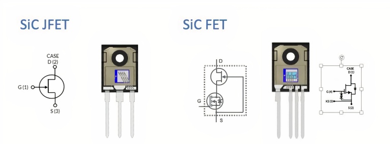
Bhalla pointed out that this combination provides all the advantages of wide-bandgap technology, such as high speed and low loss with high-temperature operation, but at the same time offers a robust gate drive with integral ESD protection. One advantage is that the gate-drive characteristics are compatible with MOSFETs and IGBTs, making them simple to integrate into existing designs. All devices may be safely driven using a conventional gate-drive voltage of 0 to 12 V or 15 V. With a real 5-V threshold voltage, good noise margin is maintained.
During the interview, Bhalla pointed out that the benefits are quantified by figures of merit (FOM), such as RDS(on) × a quantity expressible as a measure of conduction losses per unit die area, so RDS(on) × Eoss/Qoss for evaluating hard-switching applications. The FOM RDS(on) × Coss(tr), on the other hand, is critical in soft-switching applications; Bhalla said that the values of UnitedSiC devices at 750 V are about 30% lower than other solutions evaluated at 650 V. The choice of evaluating the FOM comes from the consideration of the impossibility of having an ideal null inductance that limits EMI and thus the switching frequency.
When comparing SiC FETs with SiC MOSFETs, electron mobility in the channel is much better, allowing much smaller die for the same resistance, resulting in lower capacitance and faster switching or lower RDS(on) for the same die area, which is a key measure that indicates the potential for more die per wafer for a given performance and cost savings. The interplay between on-resistance and output capacitance, which trades off for a given voltage rating to produce more or less switching loss, is quantified by Coss.
In hard-switched circuits, such as totem-pole PFC or standard two-level inverters, the low RDS(on) and low output capacitance along with near-zero voltage offer superior reverse-recovery charge (Qrr) and low Eoss/Qoss compared with previous versions. A superior and resilient integrated diode with a low forward voltage drop (1.75 V) is used in the devices. In high-frequency, soft-switched resonant converter topologies like LLC or PSFB, UnitedSiC Gen 4 SiC FETs enhance performance.
“In our devices, we don’t have a p-n junction body diode in the silicon carbide; this is instead in a MOSFET,” said Bhalla. “For hard-switching applications, the integral body diode of SiC FETs is superior in recovery speed and forward-voltage drop to Si MOSFET technologies.”
Through improved wafer-thinning processes and silver-sinter die attach, Gen 4 technology reduces heat resistance from device to case. In demanding applications, these characteristics allow for maximum power output while maintaining a minimal die temperature rise.
“Every generation, our chip becomes smaller and smaller, but the power level we need to deal with does not change; in all of this, sintering technology is critical, and we continue to improve on it,” said Bhalla. “So to address the thermal issue in Gen 4, we made the silicon carbide chip thinner; as the chip becomes thinner, the chip’s resistance drops, but the thermal resistance lowers as well. However, it is extremely difficult to handle due to the thin wafer’s proclivity for breaking. And here, a lot of engineering is required, which indicates a reduction in planning expenses, as well as the fact that we have significantly lowered RDS(on).”
UnitedSiC’s announcement includes nine new devices/packaging options in the SiC FET 750-V series, rated at 6, 9, 11, 23, 33 and 44 mΩ. All devices are available in the TO-247-4L package, while the 18-, 23-, 33-, 44-, and 60-mΩ devices are also available in the TO-247-3L package. The difference in package, Bhalla pointed out is due to the different current handling in switching modes wherein inductance can be a very critical element.
Applications
Improved switching and RDS(on) allow for more robust new applications in electric vehicles, such as traction drives and on- and off-board chargers, as well as all stages of power conversion in renewable energy inverters, power factor correction, telecommunications converters, and AC/DC or DC/DC power conversion in general. Bhalla pointed out that with a 750-V rating, there is more design flexibility for 400-V or 500-V battery/bus voltage applications.
“Our SiC devices, with their exceptionally low RDS(on) characteristics, limit the amount of heat to be dissipated to a minimum for renewable energy equipment like solar inverters and energy storage,” said Bhalla. “From a circuit protection standpoint, the SiC JFET’s low RDS(on) makes it very competitive versus low-contact–resistance relays and contactors.”
A down-conversion step with isolation from the traction battery voltage to 12 V is also included in EVs, which is generally accomplished using an LLC converter, which is presently the most efficient architecture. For optimal performance, LLC converters are switched resonantly at high frequency, and SiC FETs might be an excellent candidate.
The greatest power can be saved in traction inverters, according to UnitedSiC, and SiC FETs can replace IGBTs. Even with SiC devices, switching frequency is maintained modestly, at about 8 kHz, because the magnetic component is the motor, which does not scale down in size with higher inverter switching frequency. A single IGBT with its parallel diode may be replaced by six paralleled 6-meter SiC FETs, resulting in a 1.6% increase in semiconductor efficiency to 99.36% at 200-kW output, indicating a 3-kW reduction in power losses.
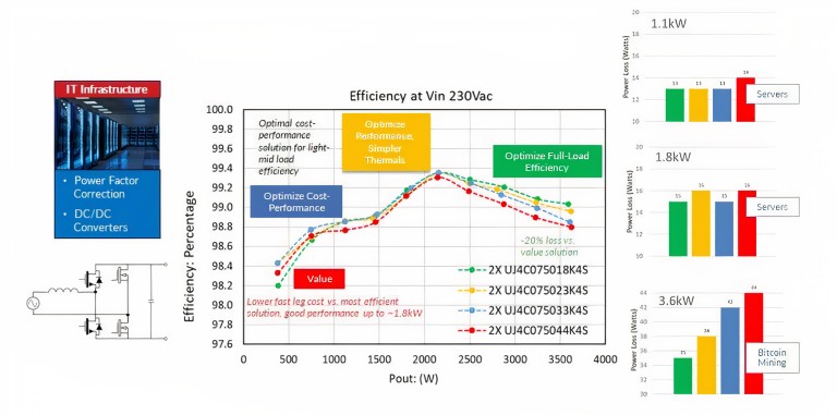
According to Bhalla, Figure 3 compares many components of a 3.6-kW totem-pole power-factor–correction (TPPFC) circuit, demonstrating the new SiC FET’s design versatility. The TO-247-4L FETs, available in either 18- or 60-meter lengths, are ideal for TPPFC applications. Figure 3 depicts the performance of the new 23-, 33-, and 44-meter 750-V SiC FETs, which achieve peak efficiencies of over 99.3%. According to UnitedSiC, the UJ4C075018K4S is a good choice for designers that want to maximize full-load efficiency while minimizing thermal management needs. The UJ4C075023K4S or UJ4C075033K4S are good choices if light- to mid-load efficiency and cost performance are important to customers. Meanwhile, designers can use the UJ4C075044K4S and UJ4C075060K4S products to customize their choices for lower-power (e.g., 1.5 kW) systems and lower-cost solutions.