
Overview
An LED circuit or LED driver is a circuit that powers an LED and is designed to provide enough current to ensure that the LED reaches the desired brightness, while at the same time the current must be limited to prevent damage to the LED. It is relatively simple to drive a single or string of low current (20-30 mA) leds, and the simplest and most economical way is to add a small resistor in the series circuit to limit the current. In the LED circuit, small changes within the power supply voltage can cause the LED to glow very bright or dim, and possibly even damage. Therefore, a series resistor is used to avoid the current flowing slightly through the LED.
The principle of LED Series Resistor
The principle behind LED Resistor involves current limitation and voltage distribution. In the LED circuit, the LED usually requires a specific current to work at the optimal brightness, and it is necessary to ensure that the current does not exceed the rated current of the LED to prevent LED damage.
The role of adding a series resistor is to limit the current and ensure that the LED is driven by the appropriate current. In order to prevent the LED from being damaged by too much current, it is necessary to limit the current through a series resistor. The series resistor regulates the current according to Ohm's law, ensuring that the LED gets the appropriate current. Current limits also help stabilize the brightness and performance of the LED.
In addition, series resistors also help to distribute voltage. The LED itself will have a certain voltage drop (Vf) when it is working forward, and the series resistance can ensure that the LED gets enough operating voltage while providing the necessary current without exceeding its rated current.
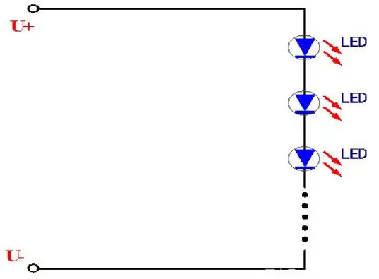
LED Series Resistor circuit
How to calculate LED Series Resistor
In order to calculate the resistance value, you need to know the input power supply voltage (Vs, generally 5V), the forward voltage (Vf) of the LED, and the value of the power supply (/) that you need to flow through the LED. The formula for calculating the ohm value of its resistance (called Ohm's law) is:
R = (Vs - Vf) / I
For example, a 5V input supply voltage and 15mA current to drive an LED with a forward voltage of 1.8V will use the following values:
Vs = 5V(5V Arduino board),
Vf = 1.8V(The forward voltage of the LED),
I = 0.015A(1mA=1/1000A,so 15mA=0.015A),
The voltage at both ends of the LED when lit is (Vs-Vf) i.e. 5V-1.8V, which is 3.2V.
Therefore, the calculated series resistance is 3.2/0.015, which is 213 ohms,
213 ohms is not a standard resistance value, so it is rounded to 220 ohms.
Positive and negative electrode identification mode
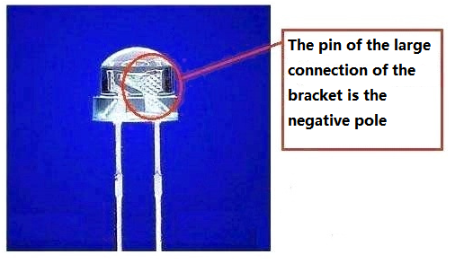
The pin of the large connection of the support is negative, and the pin of the small connection of the support is positive:
ALSO SEE: